TBM
PILOT’S OPERATING HANDBOOK
700
SECTION 7
DESCRIPTION
Page 7.6.8
Edition 1 -- November 30, 2010
Rev. 0
Starter function
Starting system consists of ”STARTER” switch located on ”ENGINE START”
panel, starter generator and ignition circuit (Refer to Paragraph ”Ignition
function”).
Starting procedure is manual. Setting ”STARTER” switch to ”ON” connects
the starter generator which drives power plant . ”STARTER” CAS message
lights on indicating that the starter generator is operating.
WARNING
ENGINE STARTING MUST BE PERFORMED BY QUALIFIED
PERSONNEL AND BY FOLLOWING PROCEDURES AND
PARAMETERS DESCRIBED IN SECTION 4 ”NORMAL PROCEDURES”
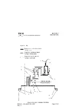
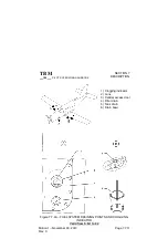
ENGINE AIR INLET
Engine air inlet is located at front lower section of engine cowling. Air inlet port
is protected against icing by a hot air flux provided by engine. Air is driven
throughout a duct in engine casing before entering engine through a
protective screen. An inertial separator system inside the air duct protects the
engine from ingesting dense particles (water, ice, fine gravels, sand).
Separator consists of two movable vanes. During normal operation, air is
channelled directly towards engine air inlet. To separate particles suspended
in the air, vanes are positioned to force engine induction air to execute a
sharp turn : under the effect of centrifugal force denser particles separate
from the air and are discharged overboard through two apertures located
under engine cowling.
Operation of inertial separator vanes is electrically controlled by ”INERT
SEP” inverter located on ”DE--ICE SYSTEM” panel. When inverter is set to
ON, an electric actuator activates vanes ; ”INERT SEP ON” CAS message
lights on when vanes have reached their maximum deflection and remains
illuminated as long as switch remains ON. Full deflection takes about 30
seconds.

