SECTION 7
DESCRIPTION
TBM
700
PILOT’S OPERATING HANDBOOK
Page 7.8.3
Edition 1 -- November 30, 2010
Rev. 0
DISTRIBUTION
Airplane electrical systems are connected to ”BUS” bars and protected by
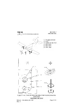
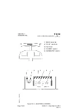
“pull--off” type circuit breakers located on R.H. side panel (See Figure 7.8.3).
In case of overload of a system, the circuit breaker triggers and switches the
system off. Allow it to cool for about three minutes, then the circuit breaker
may be reengaged (pressed down).
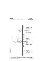
”BUS 1”, ”BUS 2” and ”BUS 3” bus bars are directly connected to main bus
bar and protected by fuses located in electrical power center.
The ”ESS BUS 1” and “ESS BUS 2” essential bus bars are connected to main
bus bar through ”ESS BUS TIE” selector set to NORM position. ”ESS BUS
TIE” selector is attached to circuit breaker panel ; NORM position is protected
and locked by a cover. Common power supply to both essential bus bars is
protected by a fuse, each bar being individually protected by a circuit breaker.
”BATT BUS” bar is directly connected to the battery ; it is protected by a fuse
located in electrical power center.
NOTE :
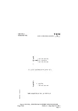
The electrical distribution of bus bars is described in Figure 7.8.2.
EMERGENCY USE
With both generators de--activated in flight, it is still possible to use battery
power to supply all airplane systems maintaining ”SOURCE” selector on
”BAT” position.
In order to save battery power, it is possible to shed the charges which are not
essential for flight safety, for that set :
-- ”ESS BUS TIE” selector to ”EMER” position
In this configuration, only ”ESS 1”, ”ESS 2” and ”BAT BUS” bars are supplied.
NOTE :
Supplying ”BUS 1”, ”BUS 2”, ”BUS 3” and (if installed) ”BUS 4” bars is always
possible, resetting temporarily ”ESS BUS TIE” selector to ”NORM” position.


