SECTION 7
DESCRIPTION
TBM
700
PILOT’S OPERATING HANDBOOK
Page 7.9.4A
Edition 1 -- November 30, 2010
Rev. 0
7.9 -- AIR CONDITIONING AND PRESSURIZATION
AIR CONDITIONING
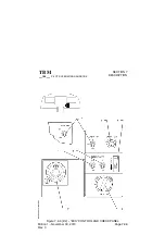
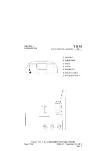
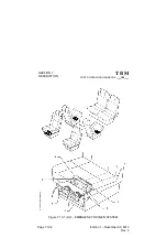
(Figure 7.9.1A)
Air conditioning system includes a flow--pressure regulation system,
temperature regulation and cooling system, control and check systems and
distribution.
Air necessary for conditioning is picked up from the engine. A two--setting
level valve regulates pressure and bleed hot air flow and may be also used as
shutoff valve. This valve is controlled by ”BLEED VALVE” switch. Hot air is
cooled by going through a temperature exchanger and a cooling turbine, then
it reduces the humidity through the water separator before entering the cabin
through a check--valve.
Temperature exchanger is located in a duct which directs cooling air. This air
is picked up outside by the NACA scoop located on L.H FWD engine cowling.
When the airplane is on ground, air flow is created by a fan which, (if ”BLEED
VALVE” switch is set to ”ON”), starts automatically.
Temperature regulation
Temperature regulation is accomplished by adding hot air to the air coming
from cooling turbine. A probe measures the temperature of conditioning air
as it enters the cabin, and acts on a temperature regulation valve which
determines hot air quantity to be added for maintaining requested
temperature in the cabin.
Distribution
Conditioned air enters the distribution box from where it is dispatched into the
cabin through two outlets located at the level of rudder pedals, a row of ports
located on the lower section of the L.H. and R.H. side upholstery and through
defogging outlets. Each seat is also provided with a swivelling and adjustable
air outlet, supplied with fresh air assisted by a fan located in pressurized area
under the floor and controlled by ”CABIN FAN” switch on ”ECS” panel.
Valid S/N 86, 88, 89, 91 to 9999


