SECTION 7
DESCRIPTION
TBM
700
PILOT’S OPERATING HANDBOOK
Page 7.12.1
Edition 1 -- November 30, 2010
Rev. 0
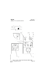
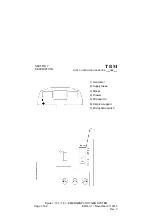
7.12 -- VACUUM SYSTEM AND INSTRUMENTS
(Figure 7.12.1)
The airplane is fitted with a vacuum system providing the suction necessary
to operate the attitude indicator, the cabin pressurization and the leading
edge deicing.
Vacuum system includes :
-- A pressure regulator
-- An ejector
-- A regulating and relief valve
-- A signalization microswitch
-- A suction gage indicator
Compressed air necessary for the ejector to create decompressed air is
taken from the power plant. The air flow is regulated before going into the
ejector which creates necessary vacuum by venturi effect.
A relief valve fixed in cabin to frame C2, maintains the vacuum for
pressurization and instrument systems. In case of pressure drop, a
microswitch, installed in the system, indicates the failure by causing the
”VACUUM LOW” CAS message to light on.
STAND--BY ATTITUDE INDICATOR
The stand--by attitude indicator, equipped with a slip indicator, provides a
visual reference of actual airplane flight attitude. An index at the top of the
indicator shows bank attitude relative to the bank scale which has index
marks at 10
°
, 20
°
, 30
°
, 60
°
and 90
°
either side of the center mark.
Pitch and roll attitudes are shown by a miniature airplane superimposed over
a symbolic horizon area divided into two sections by a white horizon bar. The
upper ”sky blue” area and the lower ”ground” area have arbitrary pitch
reference lines useful for pitch attitude control.

