SECTION 7
DESCRIPTION
TBM
700
PILOT’S OPERATING HANDBOOK
Page 7.13.1
Edition 1 -- November 30, 2010
Rev. 0
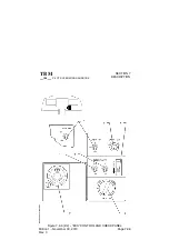
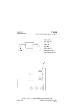
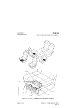
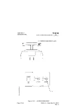
7.13 -- ICE PROTECTION EQUIPMENT
(Figure 7.13.1)
Ice protection equipment is as follows :
-- Pneumatic deice system for inboard, central and outboard wing and for
stabilizers : ”AIRFRAME DE--ICE”
-- Propeller electrical deice system : ”PROP DE--ICE”
-- Windshield electrical deice system : ”WINDSHIELD” [L.H. and (if installed)
R.H.]
-- Electrical heating system for both pitots and for the stall warning sensor :
”PITOT 1 HTR” and ”PITOT 2 & STALL HTR”
-- Turbine air inlet deice systems : ”INERT SEP”
Deicing check and control panel is located on the lower L.H. side of the
instrument panel.
WING AND EMPENNAGE DEICING
A pneumatic deice system assures protection of wing leading edges,
horizontal stabilizer, elevator horns and vertical stabilizer. The system
automatically cycles when ”AIRFRAME DE--ICE” switch is set to ”ON”.
The 67--second cycle breaks down in two inflation cycles :
-- a first cycle induces inflation of leading edges deicer boots in horizontal
stabilizer, elevator horns, vertical stabilizer and wing inboard section,
-- the second cycle induces inflation of leading edges deicer boots in wing
central and outboard sections.
During each inflation cycle, one of the two corresponding warning lights
located above ”AIRFRAME DE--ICE” switch, remains illuminated.
Wing leading edge icing inspection light -- see Chapter 7.8 Paragraph
”EXTERIOR LIGHTING”.


