SUPPLEMENT 15
“KEITH” VAPOR CYCLE COOLING SYSTEM
TBM
700
Page 9.15.5
Edition 1 -- November 30, 2010
Rev. 0
All
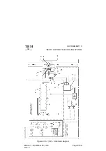
-- An evaporator fan that also provides the air circulation in the cabin as the
standard ventilation system.
TBM700A
It is installed at the same location as for the ventilation system between
frames C 13 and C 14 on R.H. side under the floor.
TBM700B
It is installed at the same location as for the ventilation system between
frames C 14 and C 15 on R.H. side under the floor.
All
The fan is supplied by the BUS 3 bar and protected by the CB 111 ”FAN”
circuit breaker.
-- A thermal expansion valve controlled by a temperature control/sensor
which is installed on the evaporator outlet.
The thermal expansion valve is screwed on the evaporator inlet.
-- Two service valves for the refrigerant.
The low pressure (LP) service valve and the high pressure (HP) service
valve are installed on a Tee bulkhead union.
The unions are screwed on a bracket riveted to the L.H. lower part of the
frame C 18.
The two valves fool--proofing is ensured by their different diameters, LP
service valve diameter is more important than HP one.
-- A sight glass, used to observe the flow of refrigerant and to determine if the
system is undercharged, is located near the HP service valve.
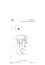
The controls and indicators are located on the ”ECS” PL23 panel in the area
identified ”AIR COND” (see Figure 9.15.2).
The control switch has three positions :
-- OFF
:
System inoperative.
-- FAN ONLY
:
Controls evaporator fan in cabin ventilation mode.
-- ON
:
Controls electric motor of the compressor/condenser
assy and fan in cabin vapor cycle cooling mode.

