TBM
700
SUPPLEMENT 15
“KEITH” VAPOR CYCLE COOLING SYSTEM
Page 9.15.6
Edition 1 -- November 30, 2010
Rev. 0
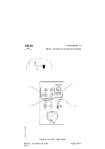
A second switch ”FAN FLOW” controls the cabin air HI or LO flow in either
FAN ONLY or ON operating positions.
A green light located next to the switches illuminates to indicate the operation
of the compressor/condenser fan motor.
A ”LT TEST” push--button enables to test the AIR COND green light.
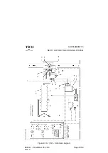
When the ”AIR COND” switch is set to ON, the compressor pressurizes the
refrigerant and discharges it to the condenser heat exchanger through the
binary pressure switch.
The condenser is cooled by ambient air drawn through an air intake by the
condenser fan and expelled overboard through an air outlet.
The refrigerant flows through the receiver drier to the thermal expansion
valve located at the evaporator inlet.
A temperature control/sensor monitoring the refrigerant temperature at the
evaporator heat exchanger outlet, pilots the thermal expansion valve which
controls the refrigerant flow through the evaporator.
The expansion of the high pressure liquid refrigerant to a low pressure liquid
extracts heat from the cabin air flowing through the evaporator and blown into
the cabin overhead duct equipped with air outlets for distribution in the cabin.
The low pressure refrigerant gas flows back to the compressor.
The system operates under two modes :
-- engine running with ”GENERATOR” selector on MAIN,
-- engine off with ”SOURCE” selector on GPU.
The system includes an automatic load shedding feature which eliminates
the compressor/condenser fan electrical motor load when :
-- ”AIRFRAME DE--ICE” switch is ON,
-- ”PROP DE--ICE” switch is ON,
-- engine is started with system fed by a GPU,
-- ”GENERATOR” selector is on ST--BY.

