TBM
PILOT’S OPERATING HANDBOOK
700
SECTION 7
DESCRIPTION
Page 7.5.2
Edition 1 -- November 30, 2010
Rev. 0
HYDRAULIC PRESSURE
Hydraulic pressure
required for landing gear operation is provided :
-- during normal operation, by an electro--hydraulic generator with integrated
reservoir,
-- during emergency extension operation by a hand pump supplied with an
auxiliary reservoir.
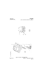
LANDING GEAR CONTROL
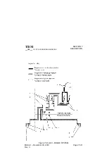
(Figure 7.5.1)
Landing gear control, located on ”LANDING GEAR” panel at the bottom of
instrument panel left part, is accomplished by an electric selector actuated
through a lever ending with a knob representing a wheel. Operation is carried
out by pulling on lever and by putting it in the desired ”UP” (retracted) or ”DN”
(extended) position. This selector controls hydraulic generator.
LANDING GEAR POSITION INDICATOR
(Figure 7.5.1)
Landing gear position indication is accomplished by 4 warning lights :
-- 3 green indicator lights (one per landing gear),
-- 1 red warning light.
NOTE :
The red warning light flashes as soon as landing gears are operating and
remains continuously on in case of locking problem.
When landing gear is correctly retracted, all warning lights are OFF.
Down--locked correct indication is when there are 3 green indicator lights ON
and 1 red warning light OFF on the landing gear indicator. All other cases
mean the gear is not down--locked.
In case of doubt about ”landing gear down--locked” position, an independant
electrical circuit provides a countercheck capability of the indication system.
Pressing the ”CHECK DN” switch located on the same panel as the warning
lights allows testing of the control circuit.
Indication panel is provided with two tests which allow checking green
indicator lights and red warning light bulbs through two distinct electric power
supplies.


