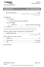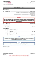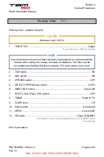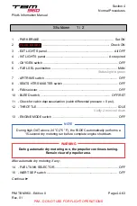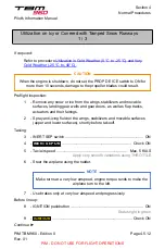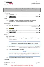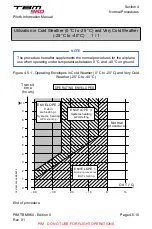
Flight into Known Icing Conditions 2 / 4
► Continuing
-
Inertial separator.
For description of deice systems, refer to
Subsection Ice Protection Equipment
.
Ice accumulation thickness is monitored by the pilot on the left-side wing leading
edge.
At night, a leading edge icing inspection light located on the fuselage left side,
activated by the ICE LIGHT pushbutton, is provided.
Boots are automatically cycling at the optimum time to assure proper ice removal.
Correct operation of the system can be checked observing the illumination in
green of the status light around AIRFRAME DE ICE pushbutton. If correct
operation cannot be confirmed, do not enter or leave as soon as possible icing
conditions.
If
AFRM DEICE FAIL
is displayed, perform procedure
.
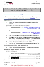
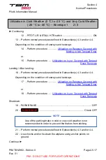
Ice Protection Procedures
CAUTION
Should conditions require it, apply these directives from beginning of taxi
onwards.
Prior to entering IMC if OAT < 5 °C and as long as under icing conditions (IMC and
OAT < 5 °C) or if
ICE DETECTED
is displayed, whichever comes first:
1
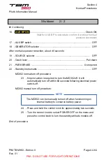
- DE ICE SYSTEM mode switch ...................................................... MAN
All deicing systems turn on
NOTE
Inertial separator position affects engine parameters, particularly TRQ
and ITT. The FADEC automatically adjusts the maximum power available
depending on the inertial separator position and in accordance with
engine operation tables – refer to
Subsection 5.8. Engine Operation
without manual adjustment of the THROTTLE.
If not, adjust engine power manually.
2
- All deicing systems ............................................................... Check ON
Continue ►
Pilot's Information Manual
Section 4
Normal Procedures
PIM TBM 960 - Edition 0
Rev. 01
Page 4.5.3
PIM - DO NOT USE FOR FLIGHT OPERATIONS

