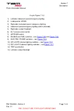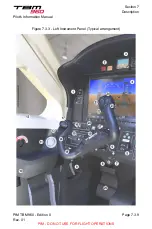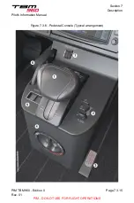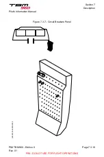
Key to Figure 7.3.3
1) DISPLAY BACKUP and SEATS HTRS MASTER panel – see
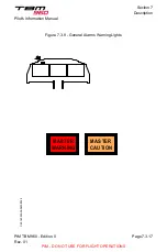
2) General alarm red and amber indicators
3) MD302
4) PFD 1
5) Landing gear configuration and control panel – see
6) Parking brake control – see
7) USB servicing plug
8) Alternate left station reception-micro jack
9) Left station rudder pedals adjusting handle
10) Left station reception-micro jacks
11) Adjustable air outlet
12) Flight conditions and instruction placard
13) AP/TRIM DISC pushbutton
14) CWS
15) Push To Talk button (PTT)
16) Circuit breaker panel lighting switch
17) Pitch & Yaw trim setting management
18) Deicing control and check panel – see
19) Paper clip
20) Hourmeter
21) MICRO/MASK switch – see
22) COM 2 (Standby / Active)
23) Stormscope clear
24) Transponder Ident sequence
25) Chronometer management
26) Left station rudder pedals
Section 7
Description
Pilot's Information Manual
PIM TBM 960 - Edition 0
Rev. 01
Page 7.3.8
PIM - DO NOT USE FOR FLIGHT OPERATIONS

