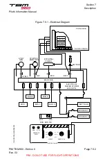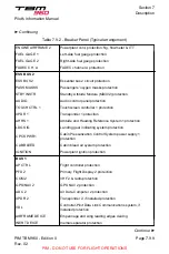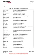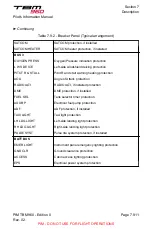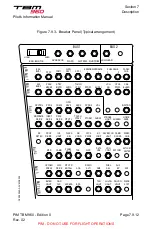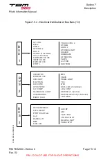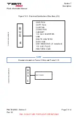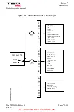
BUS 1, BUS 2, BUS 3 and BUS 4 bus bars are directly connected to main bus bar
and protected by fuses located in the electrical power system.
The ESS BUS 1 and ESS BUS 2 essential bus bars are connected to main bus
bar through the ESS BUS TIE switch set to NORM. The ESS BUS TIE switch is
attached to the breaker panel; NORM position is protected and locked by a cover.
Common power supply to both essential bus bars is protected by a fuse, located in
the EPS box, and a breaker, located in the front cargo compartment on Frame C2
right side, each bar being individually protected by a breaker.
The BATT BUS bar is directly connected to the battery; it is protected by a fuse,
located in the EPS box, and a breaker, located in the front cargo compartment on
Frame C2 left side.
NOTE
The electrical distribution of bus bars is described in
and
Table 7.9.2 - Breaker Panel (Typical arrangement)
ESS BUS TIE
BUS 1
AP SERVOS
Autopilot servo protection
FLAPS
Flaps protection
AIL TRIM
Aileron trim protection
RUD TRIM
Pitch trim protection
BUS 2
LDG GEAR
Landing gear general supply protection
ESS BUS 1
ESS BUS 1
Essential bus 1 circuit protection
PFD 1
Primary Flight Display 1 protection
COM 1
VHF 1 protection
GPS/NAV 1
GPS NAV 1 protection
ADC 1
Air Data Computer 1 protection
ENGINE AIRFRAME 1
Powerplant cont. protec.: Oil temp. & pres., torque, propeller
Continue ►
Section 7
Description
Pilot's Information Manual
PIM TBM 960 - Edition 0
Rev. 02
Page 7.9.8
PIM - DO NOT USE FOR FLIGHT OPERATIONS

