► Continuing
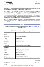
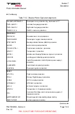
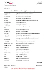
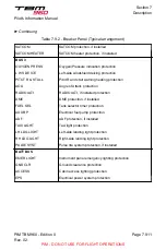
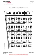
Table 7.9.2 - Breaker Panel (Typical arrangement)
ENGINE AIRFRAME 2
Powerplant cont. protection: Ng, flowmeter & ITT
FUEL GAGE 1
Left-side fuel gauge protection
FUEL GAGE 2
Right-side fuel gauge protection
FADEC CH. A
FADEC channel A protection
ESS BUS 2
ESS BUS 2
Essential bus 2 circuit protection
PASS MASKS
Passengers' oxygen masks protection
STBY INSTR
Standby Attitude Module (MD302) protection
AUDIO
Audio control panel protection
TOUCH CTRL 1
Touchscreen controller 1 protection
XPDR 1
Transponder 1 protection
AHRS 1
Attitude and Heading Reference System 1 protection
LDG SIG
Landing gear indicating system protection
CPCS PWR1
Cabin Pressurization Control System power supply 1
protection
CAB BLEED
Cabin bleed air system protection
IGNITION
Powerplant ignition protection
BUS 1
AP CTRL
Flight controller protection
PFD 2
Primary Flight Display 2 protection
COM 2
VHF 2 & radio protection
GPS/NAV 2
GPS NAV 2 protection
ADC 2
Air Data Computer 2 protection
XPDR 2
Transponder 2, if installed protection
VDL
Controller-Pilot Data Link Communications system, if
installed protection
AIRFRAME DE ICE
Empennage and wing leading edges deicing
INERT DE ICE
Inertial separator protection
Continue ►
Section 7
Description
Pilot's Information Manual
PIM TBM 960 - Edition 0
Rev. 02
Page 7.9.9
PIM - DO NOT USE FOR FLIGHT OPERATIONS

