background image

User’s Manual 

Device Structure 

 Front Panel 

1.1

 Front panel 

Figure 1-1


Table 1-1 Front panel description 

No.   

Description 

10/100/1000M Base-T RJ45 port 

10G Base-X SFP port 

Console port 

PWR (power indicator) 

SYS 

RESET 

 Rear Panel 

1.2

 Rear panel 

Figure 1-2


Table 1-2 Rear panel description 

No.   

Description 

GND screw 

AC power port 

 Indicator Description 

1.3

Table 1-3 Indicator description 

Indicator 

Status 

Description 

PWR 

ON (green light) 

The switch is powered on and the power 

module is working properly. 

OFF 

The switch is not powered on or the power 

module is not working properly. 

SYS 

Flashing (green light) 

The system is working properly. 

Summary of Contents for DH-PFS5452-48GT4XF-400

Page 1: ...User s Manual I 52 Port Managed Gigabit L2 Switch Quick Start Guide V1 0 0 ZHEJIANG DAHUA VISION TECHNOLOGY CO LTD...

Page 2: ...oided could result in property damage data loss lower performance or unpredictable result TIPS Provides methods to help you solve a problem or save you time NOTE Provides additional information as the...

Page 3: ...nctions and operations description or errors in print If there is any doubt or dispute we reserve the right of final explanation Upgrade the reader software or try other mainstream reader software if...

Page 4: ...the device in the well ventilated environment Do not block the air vent of the device Use the device at rated input and output voltage Do not dissemble the device without professional instruction Tran...

Page 5: ...1 2 1 1 Installing the Switch on the 19 inch Standard Rack 3 2 1 2 Installing the Switch on the Working Desk 4 Connecting the Cables 5 2 2 2 2 1 Connecting the Configuration Cable 5 2 2 2 Connecting t...

Page 6: ...ESET Rear Panel 1 2 Rear panel Figure 1 2 Table 1 2 Rear panel description No Description 1 GND screw 2 AC power port Indicator Description 1 3 Table 1 3 Indicator description Indicator Status Descrip...

Page 7: ...10 100 Mbps and the port is sending and receiving data OFF The RJ45 port is not connected to the corresponding device or connection failed SFP port module ON green light The SFP port is working at the...

Page 8: ...tch Unplug the power before cleaning the switch Do not wipe the switch with wet cloth and do not clean the switch with liquid Do not disassemble the switch enclosure when the switch is working and do...

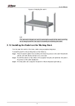
Page 9: ...switch on the clean stable and grounded working desk To install the switch on the working desk do the following Place the switch upside down carefully and clean the groove on the switch baseboard Ste...

Page 10: ...the GND cable well for lightning protection and anti electromagnetic interference To connect the GND cable do the following Remove the GND screw on the switch GND point with the cross screwdriver and...

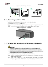
Page 11: ...ouch the golden finger of the SFP module when installing the SFP module Do not pull out the dustproof plug of the SFP module before connecting the optical fiber Do not directly insert the SFP module c...

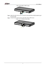
Page 12: ...dule Figure 2 6 Remove the dust cap on the LC connector of the optical fiber and the dustproof plug of Step 3 the SFP module Connect the LC connector of the optical fiber with the SFP module Step 4 Co...

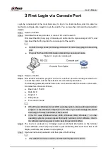
Page 13: ...tch and set the terminal communication parameters The following parameter values have to be in accordance with the values on the switch the default are shown as follows Baud rate 115200 Data bit 8 Sto...

Page 14: ...User s Manual 9 The IP address of the switch is 192 168 1 110 by default...

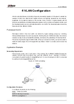
Page 15: ...etween two and several ports Dividing the port VLAN reasonably can enhance network security improve bandwidth availability and reduce the probability of broadcast storm This series of products support...

Page 16: ...config if exit SWITCH config interface GigabitEthernet 1 2 SWITCH config if switchport pvid vlan 3 SWITCH config if exit Configure the VLAN IP address Step 3 SWITCH configure terminal SWITCH config in...

Page 17: ...o keep your device such as NVR DVR IP camera etc firmware up to date to ensure the system is equipped with the latest security patches and fixes When the device is connected to the public network it i...

Page 18: ...to the device thus reducing the risk of ARP spoofing 8 Assign Accounts and Privileges Reasonably According to business and management requirements reasonably add users and assign a minimum set of per...

Page 19: ...cing 13 Construct a Safe Network Environment In order to better ensure the safety of device and reduce potential cyber risks we recommend Disable the port mapping function of the router to avoid direc...

Page 20: ...User s Manual...

Reviews: