background image


Dahua HD IR Bullet Network Camera Quick Start Guide 


10 


Connect alarm input and output terminal to external cable according to 

“Connect 

Alarm Input/output Port

”, and use insulated tape to twine connection to make it 

waterproof. 


Connect network cable to corresponding network port of the device cable according 

to 

“Install Waterproof Connector (Optional)”. 


Connect Alarm Input /Output Port 

Note 

Some models do not support alarm function, which cannot be applied to this chapter. 

Step 1 

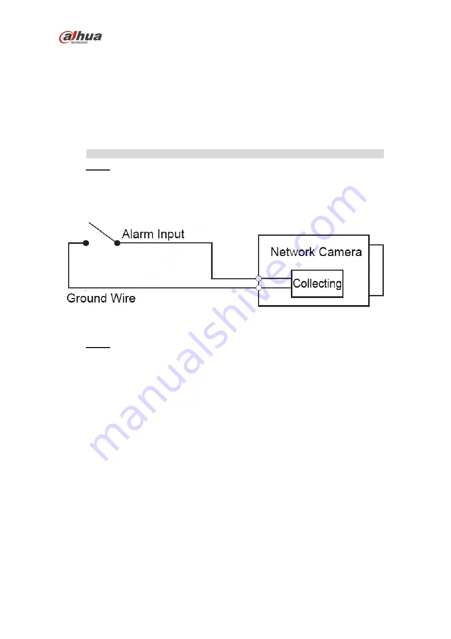
Connect alarm input device to the alarm input of I/O port. 

When the input signal is idle or grounded, the device can collect the different 

statuses of the alarm input port. When the input signal is connected to 3.3V or it 

is 

idle, the device collects the logic “1”. When the input signal is grounded, the 

device collects the logic “0”. 


Figure 2-3  


Step 2 

Connect alarm output device to the alarm output of I/O cable, alarm output is 

collector open circuit output which connects pull-up10K resistor to 3.3V 

externally. 


Mode A: 

Level application. Alarm output high and low level, alarm output is OC; it 

needs to increase pull-up resistance externally to work normally. Max external pull-

up level is 12V, max port current is 300mA (peak). After external pull-up resistance 

is increased, the default output signal is high level (external pull-up voltage), and it 

switches to low level when there is alarm output. 


Mode B:

 Switch application. Alarm output is used to drive external circuit, max 

voltage is 12V and max current is 300mA (peak), it is recommended to use an 

audible and visual alarm whose model is H103C. 

Summary of Contents for IPC-HFW2431T-ZS

Page 1: ...Dahua HD IR Bullet Network Camera Quick Start Guide Dahua HD IR Bullet Network Camera Quick Start Guide Version 1 0 0 ZHEJIANG DAHUA VISION TECHNOLOGY CO LTD...

Page 2: ...d by improper handling or installation Environment Do not aim the device at strong light to focus such as lamp light and sun light otherwise it might cause over brightness or light marks which are not...

Page 3: ...tained with grease or fingerprint use soft cloth to gently wipe the water drop or oil and wait till it is dry and then use oil free cotton cloth or lens cleaning paper soaked with alcohol or detergent...

Page 4: ...rmation 1 1 FCC conditions This device complies with part 15 of the FCC Rules Operation is subject to the following two conditions This device may not cause harmful interference This device must accep...

Page 5: ...and tool Before installation please open the package and check all the components are included Contact your local retailer as soon as possible if something is broken in your package Accessory Name Am...

Page 6: ...ramework 6 1 1 Device External Cable 6 1 2 Dimension 7 2 Device Installation 8 2 1 Install SD Card 8 2 2 Fix Device 9 2 3 Connect Device Cable 9 2 4 Adjust Device Angle 12 3 Network Configuration 13 3...

Page 7: ...ease refer to Table 1 1 and Table 1 2 for the functions of external cable and I O port respectively SN Port Port name Connector Function description 1 Power Power input port Input DC 12V 2 I O I O por...

Page 8: ...rt receive on off signal from external alarm source 2 ALARM_OUT1 Alarm output port output alarm signal to alarm device 3 ALARM_GND Ground terminal Table 1 2 1 2 Dimension Note The following figure is...

Page 9: ...ual focusing lever or reset button Step 2 Please insert the Micro SD card into the slot which is shown in Figure 2 1 the card slot is elastic so it only needs to press slightly to install the Micro SD...

Page 10: ...urface wall or ceiling and dig holes according to the hole sites marked on the installation position map Step 2 Take out the expansion bolts from the accessory bag and nail them into the holes you jus...

Page 11: ...ed to 3 3V or it is idle the device collects the logic 1 When the input signal is grounded the device collects the logic 0 Figure 2 3 Step 2 Connect alarm output device to the alarm output of I O cabl...

Page 12: ...ponding NO NC input according to the high and low level signal generated when alarm happens for alarm input device Set alarm output on the WEB alarm output is corresponding to the alarm output end whi...

Page 13: ...n insert it into the network cable Step 3 Put the main body of waterproof connector on the network port and rotate it clockwise to lock the network port and waterproof connector firmly Step 4 Put the...

Page 14: ...ce support initialization function It can implement initialization only when the device IP address 192 168 1 108 by default and the IP address of PC are in the same network segment In order to make th...

Page 15: ...d confirm password select Email Address and input email address Note The password can be set as 8 to 32 characters it can be a combination of number s letter s and symbol s with at least two kinds of...

Page 16: ...enter the planned start IP subnet mask and gateway Note Set the mode as DHCP when there is DHCP server in the network the device will automatically acquire IP address from the DHCP server Step 6 Click...

Page 17: ...Start Guide 16 Figure 3 3 Zhejiang Dahua Vision Technology Co Ltd Address No 1199 Bin an Road Binjiang District Hangzhou PRC Postcode 310053 Tel 86 571 87688883 Fax 86 571 87688815 Email overseas dahu...

Reviews: