Quick Start Guide
3
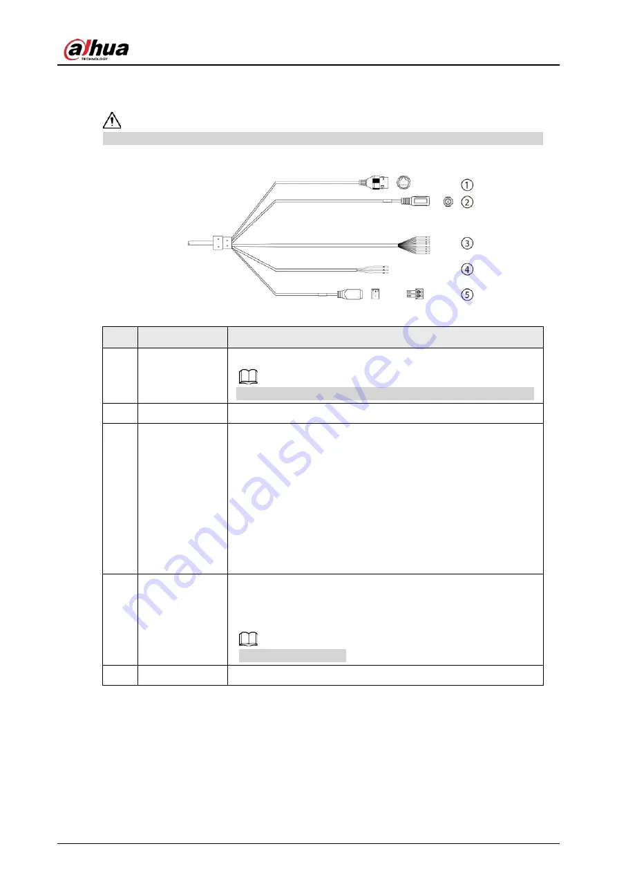
1.4 Cable Connection
Connect the cables according to the labels on the radar; otherwise the device might be damaged.
Figure 1-5 Cable connection
Table 1-3 External connection description
No.
Port name
Function
1
Network cable
(female)
Connect to a standard Ethernet cable. Support PoE power supply.
Comply with IEEE 802.3at standard when using PoE power supply.
2
Power input
12 VDC power input.
3
Alarm
●
White: Alarm input ground.
●
Blue: Alarm input.
●
Brown: Alarm output 1.
●
Pink: Alarm output 2.
●
Green: Alarm output ground 1.
●
Red: Alarm output 3.
●
Purple: Alarm output 4.
●
Light green: Alarm output 5.
●
Black: Alarm output ground 2.
4
RS–485
●
Yellow: RS–485_A.
●
Orange: RS–485_B.
●
Grey: GND.
Reserved for future use.
5
Power input
24 VAC power input.
Summary of Contents for B240
Page 1: ...Security Radar B240 Quick Start Guide ZHEJIANG DAHUA VISION TECHNOLOGY CO LTD V1 0 1...
Page 5: ...Quick Start Guide IV damage to the device...
Page 12: ...Quick Start Guide 6 Figure 2 4 Attach radar Figure 2 5 Adjusting radar angle...
Page 13: ...Quick Start Guide 7 Figure 2 6 Do not loosen the three screws Do not loosen the three screws...
Page 19: ...Quick Start Guide...


