background image


5


Installation  

ITARD-024SA high-performance narrow beam flat radar detect min speed is 10Km/h. It can not 

directly provide the vehicle direction. The width of the microwave beam level and tilt is less than 

3dB and usually it is used in the ANPR (Auto Number Plate Recognition). 

Step1 

The radar shall be installed at the transverse arm (it is 5.5-7.5M height from the ground) at the 

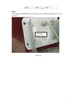
top of the lane. Please use three screws to fix the bracket and keep it standstill. See Figure 5-1. 


Figure 5-1


Step2 

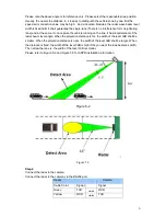
The antennae shall face the approaching vehicle. The radar wave beam shall have an angle with 

the ground. Please adjust according to the project requirements and camera snap, usually the 

distance from the centre of the radar monitor area to the projection ground distance of the radar 

ranges from 10m to 20m.  


Step3


Radar Installation Angle  

For the environment of high traffic flow or strong wind, the recommend angle shall be 23

°

.It can 

enhance the capture rate and performance is more stable.  But the shortcoming is it can not snap 

some vehicles that running on the traffic line and the vehicle snap position are about 15-17m.  

If the traffic flow is low (such as the express road), the recommend angle shall be 22

°

.In this 

situation, the capture rate may be lower than in the 23

°

, but the capture rate of the vehicles 

running on the traffic line may be higher. At the same time, the snap position is general nearer. It 

is about 16-18m. In this way, the camera can snap the human face.   


Please secure these three 

screws between the 

pedestal and the bracket.  

Summary of Contents for ITARD-024SA

Page 1: ...ITARD 024SA Radar User s Manual Version 1 0 0...

Page 2: ...i Table of Contents 1 General Introduction 1 2 Features 2 3 Specifications 3 4 Dimensions 4 5 Installation 5 6 FAQ 8 Appendix Toxic or Hazardous Materials or Elements 9 FCC Warning 10...

Page 3: ...g our device This user s manual is designed to be a reference tool for your system Please read the following safeguard and warnings carefully before you use this series product Please keep this user s...

Page 4: ...er to the radar before completing installation Always follow the instruction guide the manufacturer recommended 4 Qualified engineers needed All the examination and repair work should be done by the q...

Page 5: ...The wave beam shall not be too wide Otherwise there are several lanes in the radar detect area at the same time the radar can not distinguish the object and can not calculate the speed In the actual e...

Page 6: ...radar is small In this way it avoids the interference of reflected wave from the neighboring lane Fast responsive time guarantees the capture rate and real time feature Advanced radar signal process a...

Page 7: ...mmunication Interface StandardRS 232 Cable Definition Red DC12V or AC24V1 Black DC12V or AC24V2 White Tigger Out Yellow RS232 RXD Green RS232 TXD Orange RS232 GND Power Input DC 12V AC 24V Current 500...

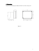
Page 8: ...4 4 Dimensions Please refer to the following figure for detailed information The unit is mm See Figure 4 1 Figure 4 1...

Page 9: ...usually the distance from the centre of the radar monitor area to the projection ground distance of the radar ranges from 10m to 20m Step3 Radar Installation Angle For the environment of high traffic...

Page 10: ...e line It has requirements of the radar beam level angle When the projection distance is far the width of the level 3dB shall be smaller When the projection distance is near the width of the level 3dB...

Page 11: ...7 Brown GND GND Step5 Connect the power cable and boot up the device you can see the indication light is on See Figure 5 4 Figure 5 4 Radar power indication light...

Page 12: ...angle Make sure it is facing the corresponding lane The radar installation angle is within the reasonable range Check the distance from the radar to the object is in the specified range The radar sen...

Page 13: ...icates that the concentration of the hazardous substance of at least one of all homogeneous materials in the parts is above the relevant threshold of the SJ T11363 2006 standard Note This manual is fo...

Page 14: ...t 15 of the FCC Rules These limits are designed to provide reasonable protection against harmful interference in a residential installation This equipment generates uses and can radiate radio frequenc...

Reviews: