Web Operations
192
5.3.3.2 Configuring Alarm Input Settings
Select
SETUP > EVENT > ALARM
.
Step 1
The
ALARM
interface is displayed. See Figure 5-78.
Alarm setting
Figure 5-78
Select alarm input type.
Step 2
Local Alarm: The alarm signal detected by the alarm input port on the Device.
IPC Disconnect: The alarm signal is generated when the IP camera is
disconnected.
Select the
Enable
check box and the channel that you want to apply the tampering
Step 3
detect function.
If
Local Alarm
is selected, select a channel from Channel 1 to Channel 7.
If
IPC Disconnect
is selected, select a channel from Channel 9 to Channel 12.
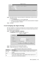
Configure the parameters. For details, see Table 5-30.
Step 4
Table 5-30 Alarm parameters description
Parameter
Description
Alarm Name
Enter a customized alarm name.
Overlay
Select the
Overlay
check box, the alarm name will display on the
channel window.
Anti-dither
Enter event detection lasting time. The system records only one event
during this period.
Type
If
Local Alarm
is selected, configure this parameter.
Normal Open: The alarm signal is disconnected normally. The alarm
is activated when alarm signal is closed.
Normal Close: The alarm signal is closed normally. The alarm is
canceled when alarm signal is disconnected.
Trigger
If
Local Alarm
is selected, configure this parameter.
High: The alarm signal is 12V/24V voltage. Low: The alarm signal is
signal ground.

