9
2.2.4
Dimensional drawing
Physical Dimensions (mm [inch])
Page 1: ...Mobile Network Video Recorder MXVR4104 I Series User s Manual V1 0 1...
Page 2: ...dify the screenshot of the WEB interface June 2022 V1 0 0 First release November 2021 Privacy Protection Notice As the device user or data controller you might collect the personal data of others such...
Page 3: ...test program and supplementary documentation There might be errors in the print or deviations in the description of the functions operations and technical data If there is any doubt or dispute we rese...
Page 4: ...uit board will cause short circuit which affect the normal operation of the Recorder and even damage the Recorder To make the Recorder work stably for a long time please regularly use the brush to rem...
Page 5: ...electrostatic or induced voltage to damage the Recorder Unplug the power cable before you remove the audio video signal cable RS 232 or RS 485 cable otherwise these ports might be damaged...
Page 6: ...m Input and Output Connection 19 2 5 1 Alarm Input Type 20 2 5 2 Alarm Input Port 21 3 Basic Settings 22 Booting up Recorder 22 Initializing Recorder 22 Logging in to Recorder 24 Configuring IP Addres...
Page 7: ...Parameters 79 5 5 1 Configuring Camera Properties 80 5 5 2 Configuring Encode Parameters 80 5 5 3 Configuring PTZ Settings 84 Configuring Network Parameters 86 5 6 1 Configuring Connection Settings 86...
Page 8: ...5 Auto Maintenance 116 7 3 1 Restarting System 116 7 3 2 Configuring Auto Start 117 7 3 3 Configuring Auto Shutdown 117 7 3 4 Delay for Auto Shutdown 117 Backing Up and Restoring 118 7 4 1 Backing Up...
Page 9: ...ice patrol urban management patrol cash carriers hazardous goods transport and logistics transport or video monitoring in harsh environments Functions Function Description Storage Stores the data in t...
Page 10: ...rts positioning function and recording linkage Recording search can be linked with vehicle moving track 3G 4G Wi Fi networks Adopts the latest wireless communication technology which has improved the...
Page 11: ...ries are complete against the packing list Instructions about front panel rear panel and labels The functions of indicator lights and ports are described in the later chapter of the Manual The labels...
Page 12: ...on when alarms occur and off when not 7 IR Receives infrared signal from remote control 8 GPS GPS status indicator Glows blue when positioning is successful and the indicator is off when positioning...
Page 13: ...d Output Connection 4 VGA interface Outputs analog video data to the connected display with VGA port For details see VGA Port introduction 5 Power cable Connects to 6V DC 36V DC power for power supply...
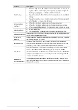
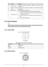
Page 14: ...V output port For details see 2 5Alarm Input and Output Connection TX RX RS 232 port sender and receiver that connect to RS 232 port A B Controls PTZ operations 2 2 3 Port Description This Manual only...
Page 15: ...V upper line 5 USB 5V upper line USB data and USB data that connect to USB port IO Reserved used for expand customization 12 12V 1A output Ground VO AV video output RX RS 232 serial port sender and re...
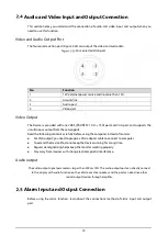
Page 16: ...8 Name Function SPK Speak negative pole 2 2 3 5 External pickup port External pickup port Name Function 12 12V output Ground Mic In that can connect to pickup Connects to earphone...
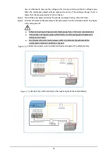
Page 17: ...9 2 2 4 Dimensional drawing Physical Dimensions mm inch...
Page 18: ...installation is complete make sure the Device is disconnected from power and do not plug or unplug components when the power is connected When installing and taking out HDD the Device electronic lock...
Page 19: ...Turn on the door locker switch Loosen the two screws at the front panel and take out the HDD carrier along the guide rail Take out HDD box Loosen two screws on the back panel of the HDD carrier take...
Page 20: ...ews to fix the HDD and HDD holder and install the HDD holder back to the Device Installing HDD Install the HDD carrier enclosure in place along the rails and then fix the HDD enclosure rear panel with...
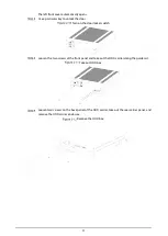
Page 21: ...card slot and SD card slot are inside the Device Gently press the left front cover The left front cover automatically opens Use a particular key to unlock the door Loosen the two screws at the front p...
Page 22: ...installation steps of locating antennas The installation process of other locating antenna is identical 2 3 3 2 1 Outside Installation Place the GPS antenna on the left front of the roof See Figure 2...
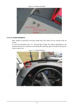
Page 23: ...requirements the antenna can be installed inside the vehicle To select the installation place it is recommended to place the antenna horizontally on the dashboard close to the windshield and make the...
Page 24: ...f the Device respectively and tighten the lugs Install the lugs onto the Device Fix the device onto the vehicle 1 Punch holes on the vehicle according to the installation dimensional drawing 2 Use scr...
Page 25: ...ain power switch through three methods is the main power switch connected to the positive or negative pole of the battery Ask the vehicle manufacture the connection modes of the main power switch of t...
Page 26: ...rding to the main power switch installation mode See Figure 2 22 and Figure 2 23 Before connecting with power cord select proper fuse 7 5A fuse is recommended The positive and negative poles of the ba...
Page 27: ...ead the following contents carefully before using the computer instead of monitor For VGA output you need to prepare a VGA adapter cable to connect to computer To extend the Device life do not keep th...
Page 28: ...t not be able to control the PTZ It is recommended to use shielded twisted pair and the shielding layer can be used for common ground Prevent interference from high voltage power make reasonable wirin...
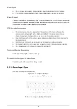
Page 29: ...nnects to speed dome with PTZ function 2 5 2 Alarm Input Port Both NO and NC are supported The GND of alarm detector is in parallel connection with COM the power supply of alarm detector should be fro...
Page 30: ...CC to work as intended Rotate the Recorder key to and rotate the vehicle key to ACC position The power indicator is on and the Recorder is ready for work For the first boot up or after restoring to th...
Page 31: ...to confirm it Then click Next Then an interface is displayed to let you fill in the password protection settings See Figure 3 3 You are recommended to use strong password The password must consist of...
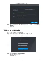
Page 32: ...ions Click Finished Logging in to Recorder You can log in to and then configure the Recorder Open the browser enter the Recorder IP address and then press Enter The Login interface appears See Figure...
Page 33: ...n the network diagram Preparation Make sure the Recorder is connected to the network properly Procedure Select SETTING NETWORK TCP IP The TCP IP interface is displayed See Figure 3 5 TCP IP Configure...
Page 34: ...ay Preferred DNS IP address of the preferred DNS Alternate DNS IP address of the alternate DNS Click OK Configuring General Settings You can configure the basic settings including time and date settin...
Page 35: ...ime interface is displayed See Figure 3 7 Date and time settings Configure Serial port parameters See Table 3 3 Table 3 3 Date and time settings parameters description Parameter Description Date forma...
Page 36: ...ate Click Manual Update to sync the Recorder time with NTP server Port The system supports TCP protocol only and the default setting is 123 Interval Enter the interval that you want the Recorder to sy...
Page 37: ...Password interface is displayed See Figure 3 9 Enter password interface Configure the password by either of the following two ways Using current Recorder password and email info Select the Using curre...
Page 38: ...r it again in the Confirm Password box Click Next The password setting interface is displayed See Figure 3 11 Password protection 5 Set password protection Click the Email Address check box and then e...
Page 39: ...starts initializing Recorder After initialization is completed see Figure 3 13 Initialization completed Click Finished 3 6 2 Adding a Remote Recorder You can add a remote Recorder manually or by searc...
Page 40: ...iption Parameter Description Manufacturer Select a manufacturer according to the actual situation Parameters might vary by manufacture Follow specific parameters on the interface Main stream The main...
Page 41: ...e added Recorder area If the remote Recorder that you want to add has the same IP address and TCP port with the existing added Recorder then this Recorder cannot be added indicates connection is succe...
Page 42: ...of manual mode and auto mode You can also enable or disable the snapshot function Auto The recording starts automatically according to the record type and recording time as configured in the recordin...
Page 43: ...ff Select the recording mode including Manual Auto and Stop Manual Top priority When the Manual check box is selected the system keeps general recording for 24 hours for the corresponding channel Auto...
Page 44: ...ble 3 6 Table 3 6 Pre record parameters description Parameter Description Channel Select a channel to configure the corresponding recording schedule If you configure the same setting for all channels...
Page 45: ...d select the recording channel 3 Click OK to return to the Record interface Click OK Click Copy to copy the settings to other channels 3 8 2 Configuring Snapshot Schedule You can configure the storage...
Page 46: ...for taking snapshots 1 Click Setting The Period interface is displayed See Figure 3 20 Period 2 Select the snapshot type and weekday and configure the period for taking snapshot 3 Click OK to return...
Page 47: ...meters description No Name Description 1 Live channels See 4 1 2 Live Channels 2 Start Talk See 4 1 3 Voice Talk 3 Instant Record Click Instant Record the recording type switches to Manual and the ico...
Page 48: ...time to be the priority according to your actual requirement Select to split the live window as necessary 6 PTZ See 4 1 4 PTZ Control 4 1 2 Live Channels Display the list of monitoring channels Monito...
Page 49: ...dio Area zoom in Click the icon and then draw a box at any area to zoom in the selected part Right click or click the icon again to restore to the original status Close Close the live view in the wind...
Page 50: ...der toward eight directions up down Left right left up right up left down right down Speed function controls the movement speed The larger the value is the faster the PTZ moves Click to display or hid...
Page 51: ...on In the PTZ setup list select Preset and then move the camera to the direction that you want to monitor 1 Click Preset and control the PTZ console to turn the camera to the target monitoring directi...
Page 52: ...supported on the external Recorder In the PTZ Setup list Click Screen Wiper Click On to turn on the screen wiper and click Off to turn off the screen wiper Clear fog Controls the warming up module of...
Page 53: ...click OK to exit the menu Click Open The OSD menu is displayed on the monitoring screen 1 1 OSD menu parameters description Parameter Description Camera Move the pointer to Camera and then click OK t...
Page 54: ...deo sections 5 Sync With Sync selected when you click in the progress bar to play back the recordings the playback time of other channels will sync with the selected channel in the following ways If t...
Page 55: ...s icon to play the video recording backward Previous frame Click this icon to jump to the previous frame You need to pause the playback before using play by frame Next frame Click this icon to play th...
Page 56: ...and the channel window and then select the record type Record type Click to start playing back video recordings Playing Video Recordings by File Name Select the date for searching for the video record...
Page 57: ...ave to the PC Search for the video recordings that you want to clip by using the calendar and timeline Select the channel number Clip the video by either of the following ways Method A Click and the a...
Page 58: ...ng Alarm Info You can view the alarm information during a fixed period On the main web interface click ALARM Alarm Info Select Type to set the alarm type to be searched for including All Motion Detect...
Page 59: ...ation Click Default to restore to factory default settings Configuring Alarm Event Settings Alarm information settings include the setting of video detection alarm input abnormality and alarm output 5...
Page 60: ...ny one of the four regions triggers alarm the channel that houses the region will give alarm 4 Click OK Configure alarm linkage parameters Table 5 1 Alarm linkage parameters Parameter Description Dela...
Page 61: ...re and select the corresponding check box to trigger a pop up message in your local host PC when an alarm event occurs Buzzer Click More and select the corresponding check box to trigger a buzzer nois...
Page 62: ...On the main web interface select ALARM Video Detection Video Tampering The Video Tampering interface is displayed Video Tampering Select Channel and select Enable to enable the video tampering detect...
Page 63: ...he 9th channel alarm Type If the Event Type is Local Alarm configure this parameter NO The alarm signal is disconnected normally The alarm is triggered when alarm signal is connected NC The alarm sign...
Page 64: ...alarm linkage tour is finished the Live interface returns to the window split mode as before the alarm occurs Anti dither Click More to set the anti dither time The system records only one alarm inpu...
Page 65: ...revail Lower Than Select Disk tab and if the Event Type is Low Space configure this parameter You can set the percentage of Disk remaining space When Disk remaining space is lower than this percentage...
Page 66: ...s an alarm Alarm output Connect the alarm device such as light and siren to the alarm output port Select the corresponding check box and set an alarm output device With the alarm linkage output port e...
Page 67: ...output port indicates there is an alarm output and indicates there is not Configuring AI Settings AI features include active and safe drive face detection and blind spot detection Only when the AI fe...
Page 68: ...h within 5 s the Recorder will compare driver face against the DSM face database If the last driver face is not in the DSM face database there is an ID exception warning once the vehicle starts to ru...
Page 69: ...paration Access to cornering lamp signal in advance Alarm Input_2 turn left Alarm Input_3 turn right After the cornering lamp of the vehicle is turned on no Lane Departure alarm will be triggered Conf...
Page 70: ...he corresponding alarm is enabled Table 5 5 ADAS parameter description Parameter Description Channel ADAS is fixed to channel 2 Forward collision warning Gives out warning if it is possible to collide...
Page 71: ...red The range is 0km h 200km h Report alarm The speed at which the Headway Monitoring Warning is uploaded The range is 0km h 200km h Alarm protection time Continuous alarm time The range is 0s 6525s T...
Page 72: ...er blind area detection When the speed is set to 0km h the blind area detection status is maintained by default When the speed is set to 30km h the blind area detection status will be maintained when...
Page 73: ...size and minimum size of the face detection region Press and hold the left mouse button and drag four corners of the blue box to adjust the size Faces smaller than the minimum size or bigger than the...
Page 74: ...Select the face image you need to view and click The system starts playing back the video file that the image belongs to Double click the playback interface to switch between full screen and small scr...
Page 75: ...ng a face library includes creating a face library adding face images and modeling faces You can create up to 20 face libraries and register up to15MB face images To protect privacy the faces in the i...
Page 76: ...ed and removed on the Recorder Click Add The Add interface is displayed See Figure 5 15 Add Enter Face Library Name and click Save The face library is saved successfully and the FACE LIBRARY 2 interfa...
Page 77: ...ace library and single add and batch import are both supported Both single add and batch import require to obtain face images from the USB flash drive Images should be smaller than 256K with resolutio...
Page 78: ...ils 1 Click Register ID The Register ID interface is displayed See Figure 5 18 Register ID 1 Click to add face photos Select a picture and fill in registration information For system display see Figur...
Page 79: ...odeling it means that the system is extracting the feature attributes of the photo Click Search to refresh the interface and Modeling succeeded is displayed If modeling fails the photo cannot be used...
Page 80: ...the numbers 1 for ID card 2 for passport and 3 for military officer passport ID No Fill in the ID number Address Enter the corresponding residence address On the face library details interface click B...
Page 81: ...ct Enable to enable the face recognition function Select the type Only AI by Device is supported Set face library 1 Click The Face Library interface is displayed See Figure 5 23 Face library 2 Select...
Page 82: ...he faces in the face library and play back the recordings On the main web interface select AI AI Search Face Recognition The Face Recognition interface is displayed See Figure 5 24 Face recognition 3...
Page 83: ...terface to switch between full screen and small screen Optional Back up files 1 Select files and click Backup The Export interface is displayed See Figure 5 26 2 Select the backup address path backup...
Page 84: ...ings and images On the main web interface click BACKUP Backup 1 Configure parameters For details see Table 5 9 Table 5 9 Backup parameters Parameter Description Storage Path Only local address is supp...
Page 85: ...ing external alarm motion detect all alarms normal record picture and all Click Search The obtained files are displayed Select the file that you want to back up and click Backup Backup 2 Click View Do...
Page 86: ...y If it is not enabled AV VGA and HDMI are switched to single screen and preview sound will not be output But it does not affect video playback and intelligent alarm voice broadcast sound Live Audio 5...
Page 87: ...te it Select a channel group and click Move up or Move down to modify the channel group sequence 5 4 3 Configuring Video Mirror Settings On the main web interface click DISPLAY Video Mirror The Video...
Page 88: ...e color purity Adjust the saturation according to the actual situation The bigger the value the more colorful the image will become Brightness Adjust the image brightness in a linear manner The bigger...
Page 89: ...er Description Smart Codec Enabling Smart Codec helps compress the images more and reduce the storage space Video enable Enable the sub stream Record type The record type of main stream is permanently...
Page 90: ...monitoring environment But the maximum bit rate value changes around the configured value Select Custom to configure bit rate value manually Reference bit rate The system recommends the optimal bit ra...
Page 91: ...lect a resolution for the captured images Quality The image quality and there are six levels in total Interval Interval of taking snapshots Select Custom to configure the snapshot interval for manuall...
Page 92: ...Display check box the Setting button is displayed Then click Setting on the right of the GPS Display and then drag it to a proper location Click OK 5 5 2 4 Storage Path You can configure the storage...
Page 93: ...s parameter Address Set the PTZ address If Local is selected for PTZ type configure this parameter Baud Rate The times of signal changes on the transmission line within one time unit The default baud...
Page 94: ...figure the ports of the device The revised settings take effect after device restart Proceed with caution Table 5 16 Connection parameters Parameter Description TCP port Transmission Control Protocol...
Page 95: ...e main stream is 0 subtype 0 the sub stream is 1 subtype 1 For example if you request the sub stream of channel 2 from a certain device the URL should be rtsp admin admin_123 192 168 1 16 554 cam real...
Page 96: ...face is displayed Wi Fi Connect to Wi Fi Auto search 1 Click Search SSID In the SSID list all available wireless networks are listed including the information such as network name security type encryp...
Page 97: ...tus After successful connection you can view the current hot spot IP address subnet mask and gateway in Wi Fi Working Info 5 6 2 2 Configuring Wi Fi Hot Spot The device can work as a hot spot to share...
Page 98: ...ettings Preparation Make sure that the device is equipped with 3G 4G module and inserted with SIM card from corresponding communication operators The dial number user name and password have been obtai...
Page 99: ...N select Customized AUTH Includes PAP CHAP and NO_AUTH protocols The system automatically recognizes and displays the enabled protocol Dial No Enter the dial number provided from the communication ope...
Page 100: ...onymous is selected the sender information is not displayed when sending an email User name Enter the user name and password of SMTP server Password Sender Sender s email address Encryption Type For a...
Page 101: ...email to check the connection after the specified interval The value ranges from 30 minutes through 1440 minutes Email test Click Test to test if emails can be sent out and received as intended If the...
Page 102: ...ver You can add devices for management by either of the following two ways Scan the QR code on the interface to download the app and register an account See App Operation Examples for details Log in t...
Page 103: ...displayed 2 Click initialize the device as needed and follow the instructions to connect the device To do so you can scan the device label or the serial number QR code of the device on the device pag...
Page 104: ...igure basic information Select the processing strategy of stopping recording and overwriting earlier recordings when Disk is full Stop When all readable and writable Disk s are full and there is no ex...
Page 105: ...You can only read data from SD card if set to read only disk Redundancy If the device is connected to two or more SD cards one of the SD cards can be set as the redundancy one for recording backup Sel...
Page 106: ...er Password Anonymous Select Anonymous if you want to log in to the server anonymously Remote directory Create a folder on FTP server If you leave it empty the system automatically creates folders bas...
Page 107: ...per the snapshot interval You can change the Interval and Mode Channel Select the channel that you want to apply the FTP settings Day Select the week day and set the time period that you want to uplo...
Page 108: ...ission will be encrypted Related devices or software shall support video decryption Private Protocol Authentication Mode You are recommended to select the Security Mode Click OK 5 8 1 2 Configuring HT...
Page 109: ...download root certificate Select SETTING SYSTEM SECURITY HTTPS The HTTPS interface is displayed Click Download Certificate The Download Certificate interface is displayed Click Open The Certificate in...
Page 110: ...rface is displayed xx xx xx xx corresponds to your device IP address or domain name Port corresponds to your HTTPS port If the default value is 443 do not enter port Just enter https xx xx xx xx to vi...
Page 111: ...ice Auto The Device Auto interface is displayed Position report device auto 2 Configure parameters Table 5 22 Device auto report parameters Parameter Description Report interval When the vehicle ACC s...
Page 112: ...e Table 5 23 Serial port setting parameters description Parameters Description Serial Port Function Select the corresponding protocol Console Upgrades programs and debug by suing the serial interface...
Page 113: ...er account authority it is recommended to give lower authority to common user accounts than advanced user account User and User Group You can manage the accounts by user and user group and the names c...
Page 114: ...User name Enter the user name and password and conform the password Password Confirm password Group Select a group for the user User MAC Enter user MAC address that is allowed to log in to the device...
Page 115: ...rface click The Modify interface is displayed Modify user Select the Modify Password check box and then enter old password new password and confirm password in corresponding boxes Select the authority...
Page 116: ...ace is displayed Group Click Add The Add interface is displayed Add group Set group name and memo A group name consists of letters numbers and special characters including _ Select the authority inclu...
Page 117: ...tual interface of the device The QR code in this document is for reference only Scanning the same QR code leads to two security codes at most To get another security code refresh the QR code interface...
Page 118: ...110 password according to the security level indication Click OK The system prompts successful operation You can use the new password to log in to the device...
Page 119: ...ure 6 1 Version Upgrading System Firmware You can import the upgrade files to upgrade the firmware The upgrade file should be a bin file During upgrade do not disconnect from power and network and res...
Page 120: ...system programs select Main for the chiplist To upgrade the MCU firmware programs select MCU for the chiplist Click Browse and select the update files you want to use Click Update The system starts u...
Page 121: ...a timely manner Back up your configuration of the system regularly Restart the device regularly Upgrade firmware in a timely manner Viewing System Information You can view device version information...
Page 122: ...face is displayed See Figure 7 2 Click Refresh and the latest network information is displayed Network information 7 2 3 Viewing Disk Information You can view the HDD information of the device includi...
Page 123: ...face is displayed See Figure 7 5 Channel information 7 2 5 Viewing Satellite Information You can view the satellite positioning information such as module state GPS status latitude and longitude and s...
Page 124: ...nd no longer powered on After the device is restarted the GPS module will be powered on again Satellite information Auto Maintenance You can configure the automatic maintenance settings such as auto r...
Page 125: ...guring auto shutdown the device automatically shuts down as per the ACC power off time and auto start setting If you have set the time for auto start there are two situations when the ACC is powered o...
Page 126: ...onfiguration You can back up all web configurations Select SETTING SYSTEM Import Export The Import Export interface is displayed Configuration import export Click Import and select the backup path The...
Page 127: ...export 2 Click Browse and then select the backup file you want to import Click Import The system pops up the restart message Click OK and the system starts importing the configurations and restart th...
Page 128: ...default configuration of the device Factory Default Click Factory Defaults and the Reboot dialog box is displayed See Figure 7 13 Then click OK and the system restarts After the device is restarted th...
Page 129: ...the Ethernet port and save path Select the Target Filter check box and then enter the IP address that you want to filter Click Start The system starts the sniffer and the data will be stored to the e...
Page 130: ...122 8 Operating by DSS Beside from web you can also remotely log in to the Recorder from Digital Surveillance System DSS For details see the manual of DSS...
Page 131: ...s from a local source 3 Q The interface shows that no SIM card is detected A Possible causes SIM card not inserted Micro SIM card reversely inserted with its notch facing outward Follow instructions o...
Page 132: ...distorted A Possible causes NTSC and PAL settings are not correct and the image becomes black and white Recorder and monitor resistance is not compatible Video network transmission distance is too far...
Page 133: ...ng first and then begin backup Backup Recorder is not compatible Backup Recorder is damaged The backup Recorder features high power and needs separate power supply 16 Q Alarm function does not work A...
Page 134: ...Q 3G 4G platform is not online A Possible causes Check if 3G 4G dial up is normal Check if local active registration is correctly set up Check if the sever terminal is correctly set up 21 Q No GPS dat...
Page 135: ...l Change the status of the check box Click the combo box the drop down list is displayed In text box click the corresponding button on the panel to enter a numeral punctuation English character small...
Page 136: ...he number of channels of the Recorder PTZ control color setting recording search recording control alarm output and main menu To use PTZ control and color setting apply to the images corresponding to...
Page 137: ...number Demand time length hour HDD capacity occupied per hour M hour Recording time calculation formula Recording time hour HDD total capacity M HDD capacity occupied per hour M hour Channel number Th...
Page 138: ...t and implement well done access control permission and key management to prevent unauthorized personnel from carrying out physical contacts such as damaging hardware unauthorized connection of remova...
Page 139: ...s we suggest that you check online users regularly to see if the device is logged in without authorization Check device log By viewing the logs you can know the IP addresses that were used to log in t...