background image


31


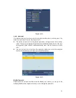
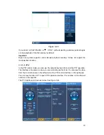
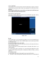
Figure 3-45 

3.3.5.7 Snapshot 

The snap function can only be valid in preview mode. The snap picture saved in the USB 
device or a FTP server. Please refer to chapter 3.3.9.3 for snapshot setup. 


Please follow the steps listed below.   
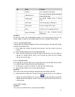
1)  Input number i+WIN, it is to select the window i for the output channel.   
2)  Input a+AUX (Please make sure you have set a+AUX as the snap shortcut button) or 

button at the top of the joystick to enable network snap.   

If you click the snapshot shortcut button directly, system snapshots the video in the first 
window by default.   


3.3.5.8 Record  

The USB device record has two types: local preview record and remote channel record. 
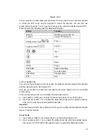
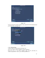
See Figure 3-46 and Figure 3-47. 

z

  Local preview record: During the preview process, select preview window to record. 


z

  Remote channel record: You can select an input a channel name to record.   

Please follow the steps listed below. 

z

  Local preview record: Input number i + WIN + REC (Please make sure you are in 

preview mode.).See Figure 3-46. 

Summary of Contents for NKB

Page 1: ...Network keyboard User s Manual V1 1 0...

Page 2: ...EW OF NAVIGATION AND CONTROLS 4 3 1 Login Logout Shutdown 4 3 1 1 Login 4 3 1 1 1 General Mode 4 3 1 1 2 Matrix Mode 5 3 1 2 Shutdown 5 3 2 Admin Operation Menu 5 3 2 1 Main Menu 5 3 2 2 System Settin...

Page 3: ...d 31 3 3 5 9 Remote Panel Simulation 33 3 3 6 Remote Operation RS232 34 3 3 6 1 The keyboard setup after COM Connection 34 3 3 6 2 Operation 35 3 3 7 Remote Operation RS485 36 3 3 7 1 The keyboard set...

Page 4: ...iii APPENDIX TOXIC OR HAZARDOUS MATERIALS OR ELEMENTS 51...

Page 5: ...This user s manual is designed to be a reference tool for the operation of your system Here you can find information about this series network keyboard features and functions Before the operation ple...

Page 6: ...le with care Do not place objects on the network keyboard 4 Qualified engineers needed All the examination and repair work should be done by the qualified service engineers We are not liable for any p...

Page 7: ...niently z Support all operations you get from DVR front panel function keys z Support keyboard lock function z Support multiple level operation rights z Support menu setup of one or more DVR s z 10 2...

Page 8: ...ase refer to the following sheet for function button information SN Name Symbol Function Number and character 0 9 It is to input number and character Click the Shift button to switch ESC Cancel exit E...

Page 9: ...hannel MON Working with the number button to select the output channel WIN Working with the number button to select the output window MULT Working with the number button to select the window split mod...

Page 10: ...AUX buttons MAC Macro setup Touch panel Display OSD Others Jog AUX menu or function buttons operation 2 3 Rear Panel This series products rear panel is shown as below See Figure 2 2 Figure 2 2 Please...

Page 11: ...ault user name is admin and password is admin Please turn the jog inner dial to select the user name and turn the shutter outer ring to move the cursor to input the password Or you can use the mouse o...

Page 12: ...mation here See Figure 3 3 Please refer to chapter 3 4 for detailed matrix mode operation Figure 3 3 3 1 2 Shutdown After you logged out the system you can press the power button to turn off the keybo...

Page 13: ...rsor or select the item After you complete current setup you can use the joystick to move the cursor to select other items For special menu item you can follow the prompt to click the ENTER button to...

Page 14: ...beeline and solidus z DST Here you can set DST time and date Please enable DST function and then click set button Here you can set start time and end time by setting corresponding date week setup z Ti...

Page 15: ...you can input IP address z Subnet mask You can input subnet mask here z DHCP It is to auto search IP When enable DHCP function you can not modify IP Subnet mask Gateway These values are from DHCP func...

Page 16: ...added it in the past z Select hotspot you want to connect and then click Connect button The WIFI new hotspot setup interface is shown as in Figure 3 9 Please note you need to disconnect current conne...

Page 17: ...ime and etc z Key Sound Here you can check the box here to enable keyboard sound function z Key Backlight Here you can check the box here to enable keyboard backlight function z Auto lock Here you can...

Page 18: ...setup See Figure 3 12 Figure 3 12 3 2 2 5 Screen Calibration You can use the screen calibration function if the touch position is not accurate with the actual position See Figure 3 13 Here you can vie...

Page 19: ...Click the Import box to import the configuration z Export Please connect the USB device to the USB port and then check the box before the device name Click the Import box to export the configuration S...

Page 20: ...in the upgrade operation Important Before the operation please make sure your upgrade file name is update bin Figure 3 15 3 2 3 Device Manager Click Device manager button you can see an interface show...

Page 21: ...earch may fail z After you searched the device its initial status is null You can view the device current status after you added it System says the device has been added means it is in the Device mana...

Page 22: ...here is for the keyboard to login the device It does not change the user name and password of the keyboard itself Figure 3 19 Delete Select the device you want to delete and then click the delete but...

Page 23: ...re 3 21 Figure 3 21 Modify Click the Modify button you can go to modify interface Here you can change serial number main stream and extra stream and protocol See Figure 3 22 Important The SN of the mo...

Page 24: ...ee Figure 3 23 Figure 3 23 Modify In Figure 3 23 click Modify button you can go to the following interface to change the output SN See Figure 3 24 Important Please make sure the output SN is unique Sy...

Page 25: ...nagement rights include add delete modify device The user management rights include add delete modify user and set devices for each user z The user account can only have the operation rights and contr...

Page 26: ...w user You need to input the user name and password See Figure 3 27 Figure 3 27 Modify User Select an ordinary user from the list and then click the Modify user button you can go to the following inte...

Page 27: ...igure 3 29 3 2 7 Shutdown Click the Shutdown button you can see system pops up a dialogue for you to confirm the operation You can logout the menu shutdown the device or reboot the system See Figure 3...

Page 28: ...input list output list remote operation advanced and remote control Figure 3 31 3 3 2 Device List The Device list is shown as below See Figure 3 32 Here you can view the device that current user can c...

Page 29: ...See Figure 3 34 Figure 3 34 Group Click Group button you can go to the following interface See Figure 3 36 You can select the group SN and then go to the group interface There are 16 input groups and...

Page 30: ...23 Figure 3 35 Figure 3 36 3 3 4 Output List The Output list interface is shown as in Figure 3 37 Figure 3 37...

Page 31: ...ut groups and you can add delete Figure 3 38 Delete Check the corresponding box first and then click Delete button you can delete the output port from the list Add Click Add button you can go to the f...

Page 32: ...mes lock after the screen auto turns off 3 3 5 1 Shortcut Operation Remote operation You can view current selected output channel on the left pane Here you can select window display mode the decoded i...

Page 33: ...Window split Mode Here is for you to set the window display mode It is to output the selected channel to the specified windows Please follow the steps listed below 1 Input number i MON it is to select...

Page 34: ...s to output a selected group via the output decoded channel Detailed function z When the channel n in the group is smaller than the output channel window amount m it is to decode dynamically System ou...

Page 35: ...input channel to the output channel respectively If the n is larger than m system decodes and outputs m output channel until the remaining input channel is smaller than m Please follow the steps list...

Page 36: ...function 3 3 5 5 PTZ In the PTZ control mode you cam use the network keyboard to control the PTZ operation The interface is the same as when you are controlling via the Web You can view the video from...

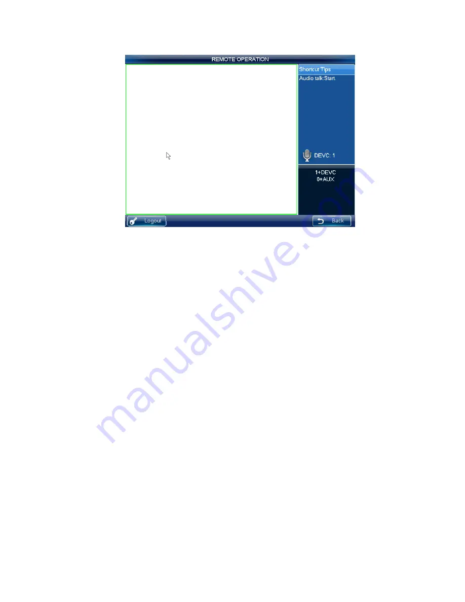
Page 37: ...directional talk between the keyboard and the selected device See Figure 3 45 Here we use a AUX to enable the audio talk function See chapter 3 3 9 3 for audio talk function setup In the local preview...

Page 38: ...on at the top of the joystick to enable network snap If you click the snapshot shortcut button directly system snapshots the video in the first window by default 3 3 5 8 Record The USB device record h...

Page 39: ...er j CAM REC See Figure 3 47 You can click STOP to stop record Figure 3 47 Important z In anytime system can only record in one mode You can not enable these two modes at the same time The remote reco...

Page 40: ...ollow the steps listed below Input number i DEVC ENTER you can begin remote panel simulation Number i is the DVR SN in the Device manager interface or the device list You can click the DEVC to exit Se...

Page 41: ...e PT button in the keyboard to enable the AUX function PTZ control and color Select the PTZ control to see DVR PTZ control menu z Input number i PT i channel number you can open the local PTZ control...

Page 42: ...ace You can use the shuttle jog to set the channel number and status Click the ENTER button to save current setup and click the ESC button to exit One window multiple window mode switch Use the jog in...

Page 43: ...485 address shall be the same with the speed dome address here 4 In the keyboard menu from the Advanced PTZ you can set protocol address baud rate data bit stop bit parity and etc You can select the p...

Page 44: ...k local preview 2 Select window display mode on the window split pane 3 Select a window double click an input channel on the input list or you can drag one channel to a window directly Now you can pre...

Page 45: ...input the number Step preset and etc from the panel You can use the keyboard to control the PTZ zoom and use joystick to control the direction You can also use mouse and touch panel You can use the to...

Page 46: ...current video and save as one picture You can press button at the top of the joystick to snapshot The picture can be saved on the flash disk or on a FTP server For detailed snapshot setup information...

Page 47: ...dress baud rate data bit stop bit and parity Figure 3 54 3 3 9 2 Modify Password The modify password interface is shown as in Figure 3 55 Here you can change the password of current user Please input...

Page 48: ...e OK button to realize the corresponding function You can input the corresponding number AUX to enable the function See Figure 3 56 Figure 3 56 Important System default AUX button is 0 you can click i...

Page 49: ...nt priority See Figure 3 58 Figure 3 58 3 3 9 5 MAC Settings The MAC interface is shown as below See Figure 3 59 Here you can enjoy a shortcut to implement a series of operations When the user is in t...

Page 50: ...e button See Figure 3 60 Important For the macro already exists it is read only Some keys do not support macro Figure 3 60 3 3 9 6 Snapshot In this interface you can save snapshot picture on a FTP ser...

Page 51: ...m does not connect to the FTP server At the same time if you have inserted a flash disk all the snapshot pictures will be saved on the flash disk If the FTP service and flash disk are both available a...

Page 52: ...apshot function 3 3 9 7 Backup In this interface you can set pre record time of the monitor video Please follow the steps listed below 1 Click Backup button on the Advanced interface You can see an in...

Page 53: ...MON is to close all video source on the selected screen and at the same time system updates the contents of the screen such as window split mode tour time and etc Double click the splicing video wall...

Page 54: ...e contents you set on the matrix end Click number 0 MON on the keyboard is to close all video sources of current screen 3 4 1 1 Set Scheme Scheme is for you to set video wall information such as windo...

Page 55: ...lect one channel and drag it to the window you selected in the first step you can output the video to the window you specified at the matrix end Or you can drag whole customized folder to the window o...

Page 56: ...once you set on the keyboard and click output video button Click save scheme button you can save current scheme setup If you have not save click reload button you can go back to previous setup Click C...

Page 57: ...e mouse and touch panel You can use the touch panel to control the positioning and PTZ Please refer to the following sheet for detailed information Button Function Number Input step preset and etc Joy...

Page 58: ...entration of the hazardous substance of at least one of all homogeneous materials in the parts is above the relevant threshold of the SJ T11363 2006 standard Note z This manual is for reference only S...

Reviews: