233
Item
Note
0 to 100. The default value is 50.
The larger the number, the strong the color is. This value has
no effect on the general brightness of the whole video. The
video color may become too strong if the value is too high. For
the grey part of the video, the distortion may occur if the white
balance is not accurate. Please note the video may not be
attractive if the value is too low. The recommended value
ranges from 40 to 60.
Gain
The gain adjust is to set the gain value. The default value may
vary due to different device models. The smaller the value, the
low the noise. But the brightness is also too low in the dark
environments. It can enhance the video brightness if the value
is high. But the video noise may become too clear.
Color mode
It includes several modes such as standard, color, bright,
gentle. Select a color mode, the sharpness, brightness,
contrast and etc can automatically switch to corresponding
setup.
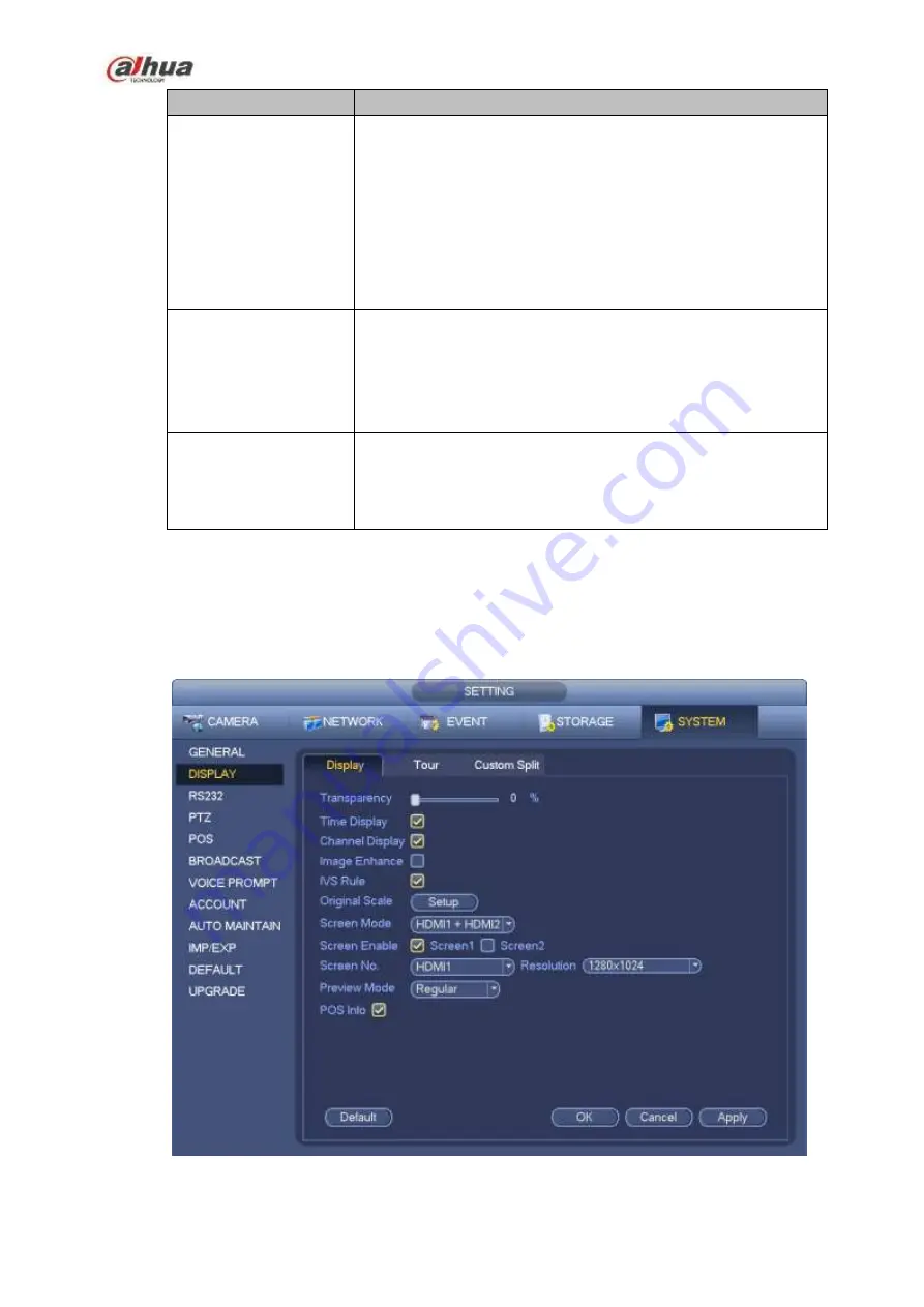
4.3.6.2 Display
From Main Menu->Setting->System->Display->Display, you can go to the following interface. See Figure
Here you can set menu and video preview effect. All you operation here does not affect the record file and
playback effect.
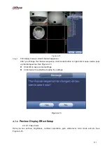
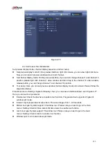
Figure 4-75
Summary of Contents for NVR100 series
Page 1: ...Dahua Network Video Recorder User s Manual V 3 0 0 ...
Page 164: ...154 Figure 3 4 3 6 5 NVR41HS W S2 Series Please refer to Figure 3 5 for connection sample ...
Page 175: ...165 Figure 3 18 3 6 19 NVR78 Series Please refer to Figure 3 19 for connection sample ...
Page 176: ...166 Figure 3 19 3 6 20 NVR78 16P Series Please refer to Figure 3 20 for connection sample ...
Page 177: ...167 Figure 3 20 3 6 21 NVR78 RH Series Please refer to Figure 3 21 for connection sample ...
Page 178: ...168 Figure 3 21 3 6 22 NVR70 Series Please refer to Figure 3 22 for connection sample ...
Page 179: ...169 Figure 3 22 3 6 23 NVR70 R Series Please refer to Figure 3 23 for connection sample ...
Page 180: ...170 Figure 3 23 3 6 24 NVR42V 8P Series Please refer to Figure 3 24 for connection sample ...
Page 181: ...171 Figure 3 24 ...
Page 193: ...183 Figure 4 14 Figure 4 15 Step 2 Set network camera login password WARNING ...
Page 201: ...191 Figure 4 24 Step 2 Click device display edit interface See Figure 4 25 ...
Page 278: ...268 Figure 4 114 Figure 4 115 ...
Page 289: ...279 Figure 4 126 Figure 4 127 ...
Page 291: ...281 Figure 4 129 Click draw button to draw the zone See Figure 4 130 ...
Page 295: ...285 Figure 4 133 Click Draw button to draw a zone See Figure 4 134 Figure 4 134 ...
Page 300: ...290 Figure 4 139 Click draw button to draw the zone See Figure 4 140 ...
Page 313: ...303 Figure 4 151 Figure 4 152 ...
Page 314: ...304 Figure 4 153 Figure 4 154 ...
Page 380: ...370 Figure 4 236 ...
Page 424: ...414 Figure 5 60 Figure 5 61 ...
Page 425: ...415 Figure 5 62 Figure 5 63 ...
Page 449: ...439 Figure 5 97 Figure 5 98 ...
Page 452: ...442 Figure 5 101 Figure 5 102 ...


