395
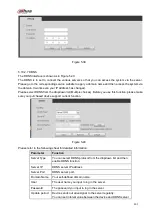
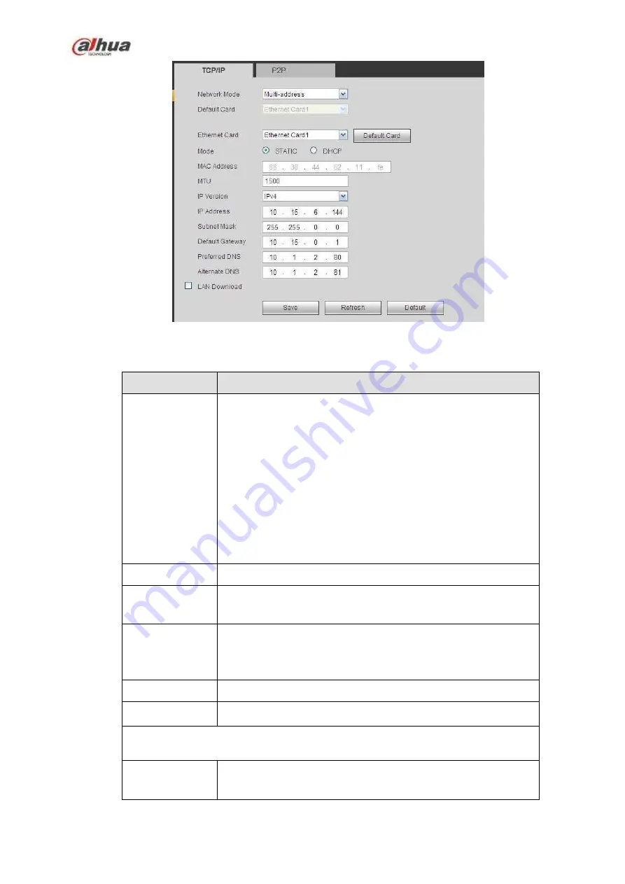
Figure 5-32
Please refer to the following sheet for detailed information.
Parameter
Function
Mode
There are two modes: static mode and the DHCP mode.
The IP/submask/gateway are null when you select the
DHCP mode to auto search the IP.
If you select the static mode, you need to set the
IP/submask/gateway manually.
If you select the DHCP mode, you can view the
IP/submask/gateway from the DHCP.
If you switch from the DHCP mode to the static mode, you
need to reset the IP parameters.
Besides, IP/submask/gateway and DHCP are read-only
when the PPPoE dial is OK.
Mac Address
It is to display host Mac address.
IP Version
It is to select IP version. IPV4 or IPV6.
You can access the IP address of these two versions.
IP Address
Please use the keyboard to input the corresponding number to
modify the IP address and then set the corresponding subnet
mask and the default gateway.
Preferred DNS
DNS IP address.
Alternate DNS
Alternate DNS IP address.
For the IP address of IPv6 version, default gateway, preferred DNS and
alternate DNS, the input value shall be 128-digit. It shall not be left in blank.
LAN load
System can process the downloaded data first if you enable this
function. The download speed is 1.5X or 2.0X of the normal
speed.
Summary of Contents for NVR100 series
Page 1: ...Dahua Network Video Recorder User s Manual V 3 0 0 ...
Page 164: ...154 Figure 3 4 3 6 5 NVR41HS W S2 Series Please refer to Figure 3 5 for connection sample ...
Page 175: ...165 Figure 3 18 3 6 19 NVR78 Series Please refer to Figure 3 19 for connection sample ...
Page 176: ...166 Figure 3 19 3 6 20 NVR78 16P Series Please refer to Figure 3 20 for connection sample ...
Page 177: ...167 Figure 3 20 3 6 21 NVR78 RH Series Please refer to Figure 3 21 for connection sample ...
Page 178: ...168 Figure 3 21 3 6 22 NVR70 Series Please refer to Figure 3 22 for connection sample ...
Page 179: ...169 Figure 3 22 3 6 23 NVR70 R Series Please refer to Figure 3 23 for connection sample ...
Page 180: ...170 Figure 3 23 3 6 24 NVR42V 8P Series Please refer to Figure 3 24 for connection sample ...
Page 181: ...171 Figure 3 24 ...
Page 193: ...183 Figure 4 14 Figure 4 15 Step 2 Set network camera login password WARNING ...
Page 201: ...191 Figure 4 24 Step 2 Click device display edit interface See Figure 4 25 ...
Page 278: ...268 Figure 4 114 Figure 4 115 ...
Page 289: ...279 Figure 4 126 Figure 4 127 ...
Page 291: ...281 Figure 4 129 Click draw button to draw the zone See Figure 4 130 ...
Page 295: ...285 Figure 4 133 Click Draw button to draw a zone See Figure 4 134 Figure 4 134 ...
Page 300: ...290 Figure 4 139 Click draw button to draw the zone See Figure 4 140 ...
Page 313: ...303 Figure 4 151 Figure 4 152 ...
Page 314: ...304 Figure 4 153 Figure 4 154 ...
Page 380: ...370 Figure 4 236 ...
Page 424: ...414 Figure 5 60 Figure 5 61 ...
Page 425: ...415 Figure 5 62 Figure 5 63 ...
Page 449: ...439 Figure 5 97 Figure 5 98 ...
Page 452: ...442 Figure 5 101 Figure 5 102 ...

