401
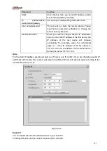
Figure 5-39
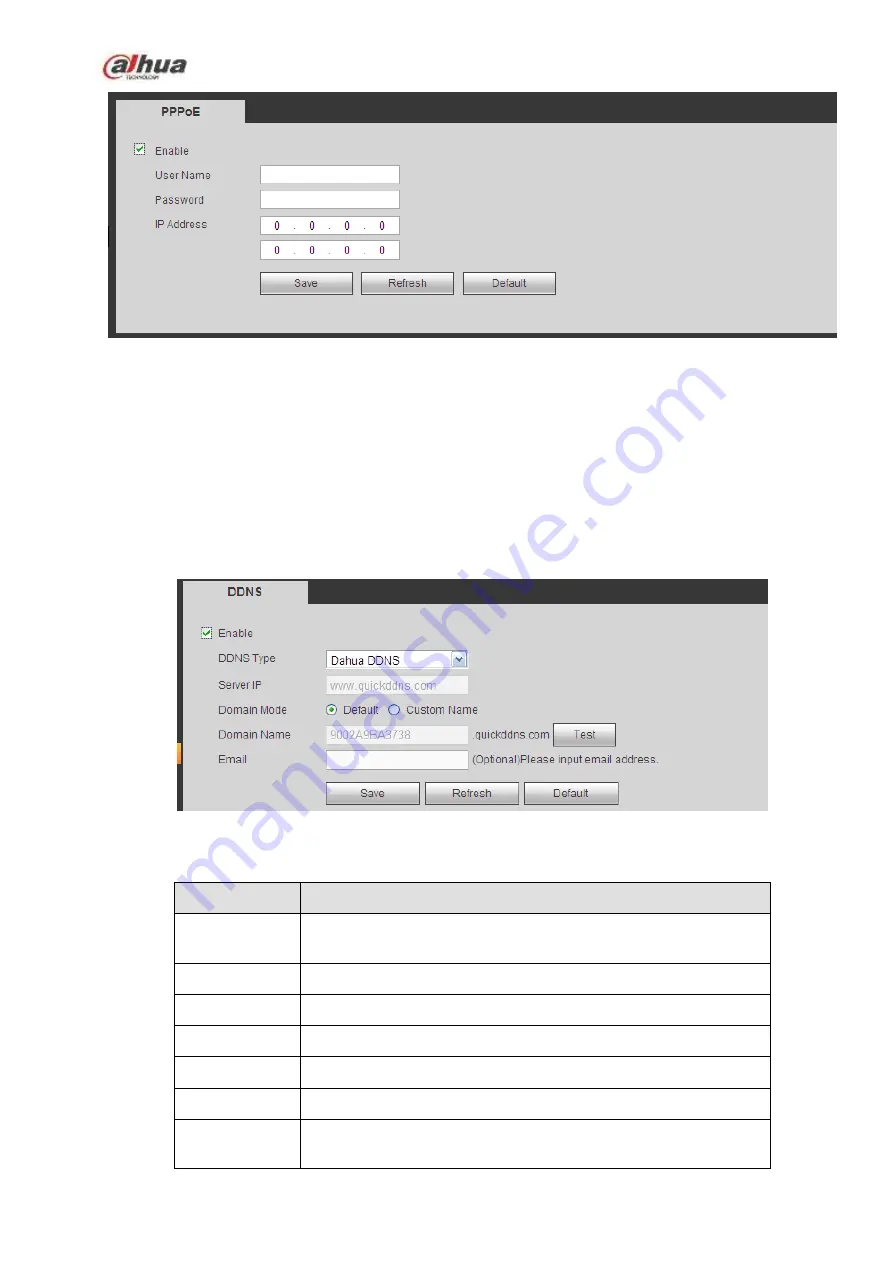
5.10.2.7 DDNS
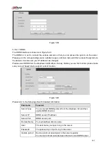
The DDNS interface is shown as in Figure 5-40.
The DDNS is to set to connect the various servers so that you can access the system via the server.
Please go to the corresponding service website to apply a domain name and then access the system via
the domain. It works even your IP address has changed.
Please select DDNS from the dropdown list (Multiple choices). Before you use this function, please make
sure your purchased device support current function.
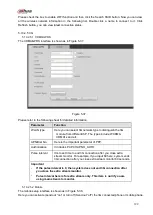
Figure 5-40
Please refer to the following sheet for detailed information.
Parameter
Function
Server Type
You can select DDNS protocol from the dropdown list and then
enable DDNS function.
Server IP
DDNS server IP address
Server Port
DDNS server port.
Domain Name Your self-defined domain name.
User
The user name you input to log in the server.
Password
The password you input to log in the server.
Update period Device sends out alive signal to the server regularly.
You can set interval value between the device and DDNS server
Summary of Contents for NVR100 series
Page 1: ...Dahua Network Video Recorder User s Manual V 3 0 0 ...
Page 164: ...154 Figure 3 4 3 6 5 NVR41HS W S2 Series Please refer to Figure 3 5 for connection sample ...
Page 175: ...165 Figure 3 18 3 6 19 NVR78 Series Please refer to Figure 3 19 for connection sample ...
Page 176: ...166 Figure 3 19 3 6 20 NVR78 16P Series Please refer to Figure 3 20 for connection sample ...
Page 177: ...167 Figure 3 20 3 6 21 NVR78 RH Series Please refer to Figure 3 21 for connection sample ...
Page 178: ...168 Figure 3 21 3 6 22 NVR70 Series Please refer to Figure 3 22 for connection sample ...
Page 179: ...169 Figure 3 22 3 6 23 NVR70 R Series Please refer to Figure 3 23 for connection sample ...
Page 180: ...170 Figure 3 23 3 6 24 NVR42V 8P Series Please refer to Figure 3 24 for connection sample ...
Page 181: ...171 Figure 3 24 ...
Page 193: ...183 Figure 4 14 Figure 4 15 Step 2 Set network camera login password WARNING ...
Page 201: ...191 Figure 4 24 Step 2 Click device display edit interface See Figure 4 25 ...
Page 278: ...268 Figure 4 114 Figure 4 115 ...
Page 289: ...279 Figure 4 126 Figure 4 127 ...
Page 291: ...281 Figure 4 129 Click draw button to draw the zone See Figure 4 130 ...
Page 295: ...285 Figure 4 133 Click Draw button to draw a zone See Figure 4 134 Figure 4 134 ...
Page 300: ...290 Figure 4 139 Click draw button to draw the zone See Figure 4 140 ...
Page 313: ...303 Figure 4 151 Figure 4 152 ...
Page 314: ...304 Figure 4 153 Figure 4 154 ...
Page 380: ...370 Figure 4 236 ...
Page 424: ...414 Figure 5 60 Figure 5 61 ...
Page 425: ...415 Figure 5 62 Figure 5 63 ...
Page 449: ...439 Figure 5 97 Figure 5 98 ...
Page 452: ...442 Figure 5 101 Figure 5 102 ...

