71
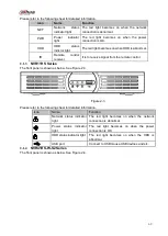
Please refer to the following sheet for detailed information.
SN
Name
Function
1
Network status indicator
light
The red light becomes on when the network
connection is abnormal.
2
Power indicator light
The red light becomes on when the power
connection is OK.
3
HDD status indictor light
The red light becomes on when HDD is abnormal.
4
USB
USB port
2.1.6
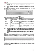
NVR42/42-P/42-8P/72/72-8P Series
The front panel is shown as below. See Figure 2-6.
Figure 2-6
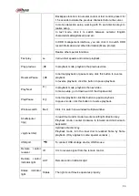
Please refer to the following sheet for front panel button information.
Name
Icon
Function
Power button
Power button, press this button for three seconds to boot up
or shut down NVR.
Shift
Shift
In textbox, click this button to switch between numeral,
English(Small/Capitalized),donation and etc.
Up/1
Down/4
、
Activate current control, modify setup, and then move up and
down.
Increase/decrease numeral.
Assistant function such as PTZ menu.
In text mode, input number 1/4 (English character G/H/I)
Left/2
Right/3
Shift current activated control,
When playback, click these buttons to control playback bar.
In text mode, input number 2(English character A/B/C)
/3(English character D/E/F)
.
ESC
ESC
Go to previous menu, or cancel current operation.
When playback, click it to restore real-time monitor mode.
Enter
ENTER
Confirm current operation
Go to default button
Summary of Contents for NVR100 series
Page 1: ...Dahua Network Video Recorder User s Manual V 3 0 0 ...
Page 164: ...154 Figure 3 4 3 6 5 NVR41HS W S2 Series Please refer to Figure 3 5 for connection sample ...
Page 175: ...165 Figure 3 18 3 6 19 NVR78 Series Please refer to Figure 3 19 for connection sample ...
Page 176: ...166 Figure 3 19 3 6 20 NVR78 16P Series Please refer to Figure 3 20 for connection sample ...
Page 177: ...167 Figure 3 20 3 6 21 NVR78 RH Series Please refer to Figure 3 21 for connection sample ...
Page 178: ...168 Figure 3 21 3 6 22 NVR70 Series Please refer to Figure 3 22 for connection sample ...
Page 179: ...169 Figure 3 22 3 6 23 NVR70 R Series Please refer to Figure 3 23 for connection sample ...
Page 180: ...170 Figure 3 23 3 6 24 NVR42V 8P Series Please refer to Figure 3 24 for connection sample ...
Page 181: ...171 Figure 3 24 ...
Page 193: ...183 Figure 4 14 Figure 4 15 Step 2 Set network camera login password WARNING ...
Page 201: ...191 Figure 4 24 Step 2 Click device display edit interface See Figure 4 25 ...
Page 278: ...268 Figure 4 114 Figure 4 115 ...
Page 289: ...279 Figure 4 126 Figure 4 127 ...
Page 291: ...281 Figure 4 129 Click draw button to draw the zone See Figure 4 130 ...
Page 295: ...285 Figure 4 133 Click Draw button to draw a zone See Figure 4 134 Figure 4 134 ...
Page 300: ...290 Figure 4 139 Click draw button to draw the zone See Figure 4 140 ...
Page 313: ...303 Figure 4 151 Figure 4 152 ...
Page 314: ...304 Figure 4 153 Figure 4 154 ...
Page 380: ...370 Figure 4 236 ...
Page 424: ...414 Figure 5 60 Figure 5 61 ...
Page 425: ...415 Figure 5 62 Figure 5 63 ...
Page 449: ...439 Figure 5 97 Figure 5 98 ...
Page 452: ...442 Figure 5 101 Figure 5 102 ...


