187
VGA+HDMI2: It is for dual-screen operation. Please select from the dropdown list according to your
actual situation. Click Apply button, system needs to restart to activate new setup. For example,
32+4 means for VGA, system max supports 32-window split and for HDMI2, system max supports
4-window split.
Please note this function is for some series only.
Color mode: Please select from the dropdown list. It is to set video color mode.
Transparency: Here is for you to adjust menu transparency. The higher the value is, the better
transparent the menu is.
Channel name: Here is for you to modify channel name. System max support 25-digit (The value
may vary due to different series). Please note all your modification here only applies to NVR local
end. You need to open web or client end to refresh channel name.
Time display: You can select to display time or not when system is playback.
Channel display: You can select to channel name or not when system is playback.
Image enhance: Check the box; you can optimize the margin of the preview video.
Original scale: Check the box here to select a corresponding channel; it can restore video original
scale.
Click OK button to save current setup.
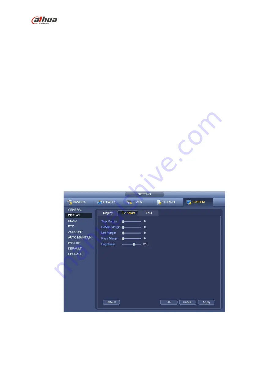
4.7.4.3 TV adjust
Note
Some series product supports TV adjust function. This function is disabled by default.
From Main Menu->Setting->System->Display->TV adjust; you can go to the following interface. See
Figure 4-38. Here you can set margins and brightness.
Figure 4-39
4.7.5
Preview Tour Parameters
Set preview display mode, channel display sequence and tour setup.
Summary of Contents for nvr4208-8p
Page 1: ...Dahua Network Video Recorder User s Manual V 2 7 0 ...
Page 160: ...145 Figure 3 4 3 5 5 NVR41HS W S2 Series Please refer to Figure 3 5 for connection sample ...
Page 171: ...156 Figure 3 18 3 5 19 NVR78 Series Please refer to Figure 3 19 for connection sample ...
Page 172: ...157 Figure 3 19 3 5 20 NVR78 16P Series Please refer to Figure 3 20 for connection sample ...
Page 173: ...158 Figure 3 20 3 5 21 NVR78 RH Series Please refer to Figure 3 21 for connection sample ...
Page 174: ...159 Figure 3 21 3 5 22 NVR70 Series Please refer to Figure 3 22 for connection sample ...
Page 175: ...160 Figure 3 22 3 5 23 NVR70 R Series Please refer to Figure 3 23 for connection sample ...
Page 176: ...161 Figure 3 23 3 5 24 NVR42V 8P Series Please refer to Figure 3 24 for connection sample ...
Page 177: ...162 Figure 3 24 ...
Page 243: ...228 Figure 4 89 Figure 4 90 ...
Page 244: ...229 Figure 4 91 Figure 4 92 ...
Page 259: ...244 Figure 4 110 Figure 4 111 ...
Page 260: ...245 Figure 4 112 Figure 4 113 ...
Page 261: ...246 Figure 4 114 Figure 4 115 ...
Page 263: ...248 Figure 4 117 Figure 4 118 ...
Page 355: ...340 Figure 5 55 Figure 5 56 ...
Page 356: ...341 Figure 5 57 Figure 5 58 Figure 5 59 ...
Page 367: ...352 Figure 5 73 Figure 5 74 ...


