74
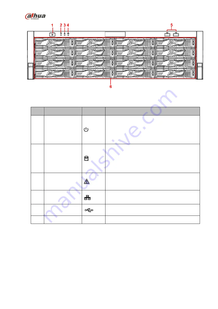
Figure 2-14
Please refer to the following sheet for front panel button information.
SN
Name
Icon
Function
1
Power button
Press it once to turn on the device.
Press it for a long time to turn off the device (
Usually
we do not recommend
).
Press power button for a long time or pull out the
power cable may result in device auto restart.
2
System
HDD
Indicator light
The blue light flashes when system is reading or
writing the system HDD.
In the system HDD, there are device important
configuration file, factory default configuration file,
device initial boot up data.
3
Alarm indicator light
The alarm indicator light becomes on once an alarm
occurred. It becomes on via the software detection.
The alarm includes local alarm, no disk and etc.
4
Network
indicator
light
The network indicator light is blue and it flashes when
you connect the device to the network.
5
USB2.0 port
Connect to USB2.0 storage device, mouse, USB
burner and etc.
6
16 HDD slot
-
/
After you remove the front panel, you can see there are 16 HDDs. From the left to the right and from the
top to the bottom, it ranges from 1~4, 5~8, 6~12, 13~16. See Figure 2-15.
You can see there are two indicator light s on the HDD bracket.
The power indicator light is at the top. The light is yellow after you connected the device to the power.
The read-write indicator light is at the bottom. The blue light flashes when system is reading or
writing the data.
Summary of Contents for nvr4208-8p
Page 1: ...Dahua Network Video Recorder User s Manual V 2 7 0 ...
Page 160: ...145 Figure 3 4 3 5 5 NVR41HS W S2 Series Please refer to Figure 3 5 for connection sample ...
Page 171: ...156 Figure 3 18 3 5 19 NVR78 Series Please refer to Figure 3 19 for connection sample ...
Page 172: ...157 Figure 3 19 3 5 20 NVR78 16P Series Please refer to Figure 3 20 for connection sample ...
Page 173: ...158 Figure 3 20 3 5 21 NVR78 RH Series Please refer to Figure 3 21 for connection sample ...
Page 174: ...159 Figure 3 21 3 5 22 NVR70 Series Please refer to Figure 3 22 for connection sample ...
Page 175: ...160 Figure 3 22 3 5 23 NVR70 R Series Please refer to Figure 3 23 for connection sample ...
Page 176: ...161 Figure 3 23 3 5 24 NVR42V 8P Series Please refer to Figure 3 24 for connection sample ...
Page 177: ...162 Figure 3 24 ...
Page 243: ...228 Figure 4 89 Figure 4 90 ...
Page 244: ...229 Figure 4 91 Figure 4 92 ...
Page 259: ...244 Figure 4 110 Figure 4 111 ...
Page 260: ...245 Figure 4 112 Figure 4 113 ...
Page 261: ...246 Figure 4 114 Figure 4 115 ...
Page 263: ...248 Figure 4 117 Figure 4 118 ...
Page 355: ...340 Figure 5 55 Figure 5 56 ...
Page 356: ...341 Figure 5 57 Figure 5 58 Figure 5 59 ...
Page 367: ...352 Figure 5 73 Figure 5 74 ...


