188
Set preview display mode: On the preview interface, right click mouse, you can view right-click menu.
Now you can select preview window amount and channel.
Set channel display mode: On the preview interface, if you want to change channel 1 and channel 16
position, please right click channel 1 video window and then drag to the channel 16 video window,
release button, you can change channel 1 and channel 16 position.
Tour setup: Here you can set preview window channel display mode and interval. Please follow the
steps listed below.
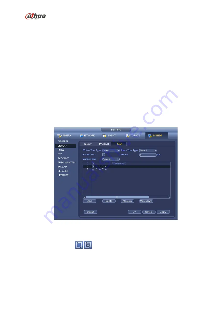
From Main menu->Setting->System->Display->Tour, you can see an interface shown as in Figure 4-40.
Here you can set tour parameter.
Enable tour: Check the box here to enable tour function. The general tour supports all types of
window split mode.
Interval: Input proper interval value here. The value ranges from 1-120 seconds.
Motion tour type: System support 1/8-window tour. Please note you need to go to the main
menu->Setting->Event->Video detect->Motion detect to enable tour function.
Alarm tour type: System support 1/8-window tour. Please note you need to go to the main
menu->Setting->Event->Alarm to enable tour function.
Window split: It is to set window split mode.
Figure 4-40
Tips
On the navigation bar, click
/
to enable/disable tour.
Click Save button to save current setup.
4.8 Fish eye (Optional)
Please note this function is for some series only.
4.8.1
Fish eye de-warp during preview interface
On the preview interface, select fish eye channel and then right click mouse, you can select fish eye. See
Summary of Contents for nvr4208-8p
Page 1: ...Dahua Network Video Recorder User s Manual V 2 7 0 ...
Page 160: ...145 Figure 3 4 3 5 5 NVR41HS W S2 Series Please refer to Figure 3 5 for connection sample ...
Page 171: ...156 Figure 3 18 3 5 19 NVR78 Series Please refer to Figure 3 19 for connection sample ...
Page 172: ...157 Figure 3 19 3 5 20 NVR78 16P Series Please refer to Figure 3 20 for connection sample ...
Page 173: ...158 Figure 3 20 3 5 21 NVR78 RH Series Please refer to Figure 3 21 for connection sample ...
Page 174: ...159 Figure 3 21 3 5 22 NVR70 Series Please refer to Figure 3 22 for connection sample ...
Page 175: ...160 Figure 3 22 3 5 23 NVR70 R Series Please refer to Figure 3 23 for connection sample ...
Page 176: ...161 Figure 3 23 3 5 24 NVR42V 8P Series Please refer to Figure 3 24 for connection sample ...
Page 177: ...162 Figure 3 24 ...
Page 243: ...228 Figure 4 89 Figure 4 90 ...
Page 244: ...229 Figure 4 91 Figure 4 92 ...
Page 259: ...244 Figure 4 110 Figure 4 111 ...
Page 260: ...245 Figure 4 112 Figure 4 113 ...
Page 261: ...246 Figure 4 114 Figure 4 115 ...
Page 263: ...248 Figure 4 117 Figure 4 118 ...
Page 355: ...340 Figure 5 55 Figure 5 56 ...
Page 356: ...341 Figure 5 57 Figure 5 58 Figure 5 59 ...
Page 367: ...352 Figure 5 73 Figure 5 74 ...


