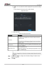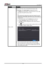
2. Click the target place on the video of fisheye camera, or move
to the target place.
The video at upper-left corner is the fisheye camera screen, and the video at upper-
right corner is the speed dome screen.
3. Adjust position through the icons below the speed dome screen to make the center of
speed dome identical to the
of fisheye camera.
The
on the speed dome screen is the center of speed dome.
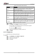
Table 5-52 Icon description
Icon
Description
,
Zoom in and zoom out.
,
Adjust resolution.
,
Adjust height.
Electronic mouse. You can use this icon to move the mouse to control
PTZ direction.
Quick positioning key. Click this icon to select a place, and the screen will
be focused and centered on the selected place.
4. Click Add.
The calibration point will be displayed on the list at lower-right corner.
Step 5
Click to save the newly added calibration point.
Step 6
Repeat Step 2 to Step 5 to add more calibration points.
Set 3–8 calibration points for a speed dome.
Step 7
Click Apply.
5.9.17 Video Quality Analytics
When conditions such as blurry, overexposure, or the color changes appear on the screen, the
system triggers the alarm.
●
This function takes effect only when the remote IPC supports video quality analytics.
●
This function is available on select models.
5.9.17.1 Configuring Video Quality Analytics
Procedure
Step 1
Select Main Menu > AI > Parameters > Video Quality Analytics.
Step 2
Select a channel and click Enable.
User's Manual
311
Summary of Contents for NVR5208-EI
Page 1: ...ZHEJIANG DAHUA VISION TECHNOLOGY CO LTD V2 3 6 Network Video Recorder User s Manual...
Page 97: ...Figure 2 116 Alarm input port 1 User s Manual 81...
Page 146: ...Figure 5 9 Unlock pattern login User s Manual 130...
Page 160: ...Figure 5 24 AcuPick human detection User s Manual 144...
Page 164: ...Figure 5 28 Shortcut menu 1 User s Manual 148...
Page 230: ...Figure 5 93 AcuPick human detection User s Manual 214...
Page 404: ...Figure 5 267 Pattern login User s Manual 388...
Page 441: ...Figure 5 305 File management Step 2 Click Add User s Manual 425...
Page 462: ...Figure 5 329 Shutdown 2 User s Manual 446...
Page 489: ......


