background image


To avoid personal injury, do not touch any exposed wire, terminal and areas with danger voltage of 
the Device and do not dismantle parts or plug connector during power on. 


Before connecting power, make sure that the power supply conforms to the power supply 
requirements on the Device label. Otherwise, it might cause device damage. 

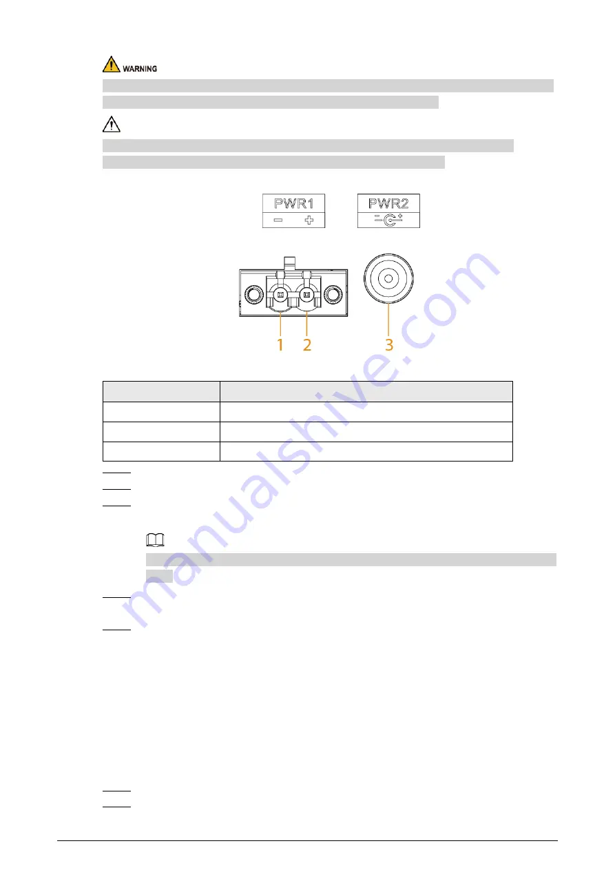
Figure 4-2 Power terminal 


Table 4-1 Power terminal description 

No. 

DC Wiring Definition 

PWR1- 

PWR1+ 

PWR2 

Step 1 

Connect the Device to ground. 

Step 2 

Take off the power terminal plug from the Device. 

Step 3 

Insert one end of the power cable into the power terminal plug according to the 
requirement. 


The sectional area of power cable needs to be more than 0.75 mm² (max sectional area 2.5 
mm²). 

Step 4 

Insert the plug which is connected to power cable back to the corresponding power 
terminal socket of the Device. 

Step 5 

Connect the other end of power cable to the corresponding external power supply system 
according to the power supply requirement marked on the Device, and check if the 
corresponding power indicator light of the Device is on, it means power connection is 
correct if the light is on. 

4.3 Connecting SFP Ethernet Port 

We recommend wearing antistatic gloves, then the antistatic wrist before installing SFP module. 
Make sure that the antistatic wrist and the surface of the gloves are in good contact. 
Step 1 

Lift the handle of SFP module upward vertically and make it get stuck to the top hook. 

Step 2 

Hold the SFP module on both sides and push it gently into the SFP slot until the SFP 

Summary of Contents for PFS3005-5ET-V2

Page 1: ...Hardened Managed Switch Quick Start Guide V1 0 1...

Page 2: ...e 2022 V1 0 0 First release February 2022 Privacy Protection Notice As the device user or data controller you might collect the personal data of others such as their face fingerprints and license plat...

Page 3: ...the functions operations and technical data If there is any doubt or dispute we reserve the right of final explanation Upgrade the reader software or try other mainstream reader software if the manual...

Page 4: ...away from dampness dust and soot Put the device in a well ventilated place and do not block its ventilation Use an adapter or cabinet power supply provided by the manufacturer The power supply must co...

Page 5: ...ns Do not drop or splash liquid onto the device and make sure that there is no object filled with liquid on the device to prevent liquid from flowing into it Operating temperature 30 C 22 F to 65 C 14...

Page 6: ...ator 2 2 1 Front Panel 2 2 2 Side Panel 3 3 Installation 4 4 Wiring 5 4 1 Connecting GND 5 4 2 Connecting Power Cord 5 4 3 Connecting SFP Ethernet Port 6 4 4 Connecting Ethernet Port 8 4 5 Connecting...

Page 7: ...on to iLinksView the Device can offer multiple working modes and meet different requirements under different scenarios The Device is applicable for use in different scenarios including corridors facto...

Page 8: ...ront panel The following are all the ports and indicators on the front panel of the Device Table 2 1 Description of front panel No Description 1 Reset button Press and hold it for more than 5 s and re...

Page 9: ...ed to device Off Not connected to device Flashes Transmitting 1000 Mbps data 6 10 100 Mbps adaptive PoE port 7 Single port connection or data transmission status indicator Link Act On Connected to dev...

Page 10: ...ail mount Hang the hook on the rail press the Device to make the buckle stuck into the rail The width of the guide rail supported by the Device is 50 mm Figure 3 1 DIN rail Table 3 1 Component descrip...

Page 11: ...nclosure GND with a cross screwdriver Step 2 Connect one end of the GND cable with the cold pressed terminal and fix it on the enclosure GND with the GND screw Step 3 Connect the other end of the GND...

Page 12: ...needs to be more than 0 75 mm max sectional area 2 5 mm Step 4 Insert the plug which is connected to power cable back to the corresponding power terminal socket of the Device Step 5 Connect the other...

Page 13: ...optical port directly when the Device is powered on When installing the SFP optical module do not touch the gold finger of the SFP optical module Do not remove the dust plug of the SFP optical module...

Page 14: ...gure 4 6 Cable connection The cable connection of RJ 45 connector conforms to the standard 568B 1 orange white 2 orange 3 green white 4 blue 5 blue white 6 green 7 brown white 8 brown 4 5 Connecting P...

Page 15: ...dmin Password Web admin iLinksView lt_91_il_02_nmp When using the iLinksView to manage the Device make sure that the username and password must be the same as that you have set in the iLinksView other...

Page 16: ...We suggest that you download and use the latest version of client software Nice to have recommendations to improve your device network security 1 Physical Protection We suggest that you perform physic...

Page 17: ...inder encrypted transmission will cause some loss in transmission efficiency 11 Secure Auditing Check online users we suggest that you check online users regularly to see if the device is logged in wi...

Reviews: