The Grand Tour
15
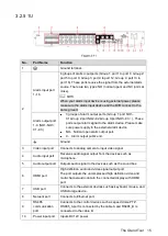
3.2.5
1U
No.
Port Name
Function
1
Ground terminal.
2
Alarm input port
1–16
4 groups of alarm input ports (Group 1: port 1 to port 4; Group 2:
port 5 to port 8; Group 3: port 9 to port 12; Group 4: port 13 to
port 16). These ports receive the signal from the external alarm
source. There are two types: NO (normal open) and NC (normal
close).
When your alarm input device is using external power, please
make sure the alarm input device and the DVR connect to the
same ground.
Alarm output port
1–3 (NO1–NO3;
C1–C3)
3 groups of alarm output ports. (Group 1: port NO1–
C1,Group 2:port NO2–C2,Group 3:port NO3–C3
)
). These
ports output alarm signal to the alarm device. Please make
sure power supply to the external alarm device.
NO
:
Normal open alarm output port.
C
:
Alarm output public end.
Ground.
3
Video input port
Connects to analog camera to input video signal.
4
Audio input port
Receives audio signal output from the devices such as
microphone.
5
Audio output port
Outputs audio signal to the devices such as the sound box.
6
HDMI port
High definition audio and video signal output port.
The port outputs the uncompressed high definition video and
multi-channel audio data to the connected display with HDMI
port.
7
USB port
Connects to the external devices such as keyboard, mouse, and
USB storage device.
8
Network port
Connects to Ethernet port.
9
RS485
communication
port
Connects to the control devices such as speed dome PTZ.
RS485_A port is connected by the cable A and RS485_B is
connected to the cable B.
10
Power input port
Inputs DC 12V power.
Summary of Contents for Smart 1U
Page 1: ...DIGITAL VIDEO RECORDER User s Manual V1 0 0...
Page 30: ...Connecting Basics 20...
Page 80: ...Local Configurations 70 No Icon Description...
Page 181: ...Local Configurations 171 Select the Enable check boxes to enable IoT function See Figure 5 152...
Page 234: ...Local Configurations 224...
Page 280: ...Glossary 270 Abbreviations Full term VGA Video Graphics Array WAN Wide Area Network...
Page 298: ...Earthing 288...


