Earthing
284
arrestor with the signal port, it can cut the channel of the thunderstorm to the device, and
on the other hand, it can discharge the current to the ground to guarantee the device
proper work. The signal lightning arrester has many specifications, and widely used in
many devices such as telephone, network, analog communication, digital communication,
cable TV and satellite antenna. For all the input port, especially those from the outdoor, you
need to install the signal lightning arrester.
Antenna feed cable lightning arrester: It is suitable for antenna system of the transmitter or
the device system to receive the wireless signal. It uses the serial connection too.
Please note, when you select the lighting arrester, please pay attention to the port type and the
earthing reliability. In some important environment, you need to use special shielded cable. Do
not parallel connect the thunder proof ground cable with the ground cable of the lightning rod.
Please make sure they are far enough and grounded respectively.
Appendix 7.2
The Earthing Modes
We all know the earthing is the most complicated technology in the electromagnetism
compatibility design since there is no systematic theory or module. The earthing has many
modes, but the selection depends on the system structure and performance.
The following are some successfully experience from our past work.
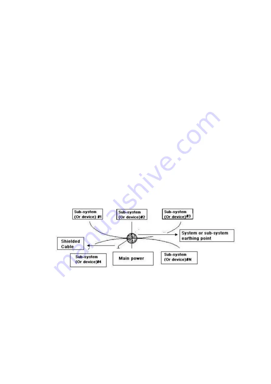
One-point ground:
In the following figure you can see there is a one-point ground. This
connection provides common point to allow signal to be transmitted in many circuits. If
there is no common point, the error signal transmission occurred. In the one-point ground
mode, each circuit is just grounded only and they are connected at the same point. Since
there is only one common point, there is no circuit and so, there is no interference.
Multiple-point ground:
In the following figure, you can see the internal circuit uses the
chassis as the common point. While at the same time, all devices chassis use the earthing
as the common point. In this connection, the ground structure can provide the lower
ground resistance because when there are multiple-point grounds; each ground cable is as
short as possible. And the parallel cable connection can reduce the total conductance of
the ground conductor. In the high-frequency circuit, you need to use the multiple-point
ground mode and each cable needs to connect to the ground. The length shall be less than
the 1/20 of the signal wavelength.
Summary of Contents for Smart 1U
Page 1: ...DIGITAL VIDEO RECORDER User s Manual V1 0 0...
Page 30: ...Connecting Basics 20...
Page 80: ...Local Configurations 70 No Icon Description...
Page 181: ...Local Configurations 171 Select the Enable check boxes to enable IoT function See Figure 5 152...
Page 234: ...Local Configurations 224...
Page 280: ...Glossary 270 Abbreviations Full term VGA Video Graphics Array WAN Wide Area Network...
Page 298: ...Earthing 288...


