157
Appendix A Mouse Control
Note: This section is designed for mouse operation with right hand.
User must connect a mouse to via USB interface in order to access the menu for mouse
operation.
Left click
mouse
System pops up password input dialogue box if you have not logged in.
When you have selected one menu item, left click mouse to view menu
content.
Implement the control operation.
Modify checkbox or motion detection status.
Click combo box to pop up drop down list
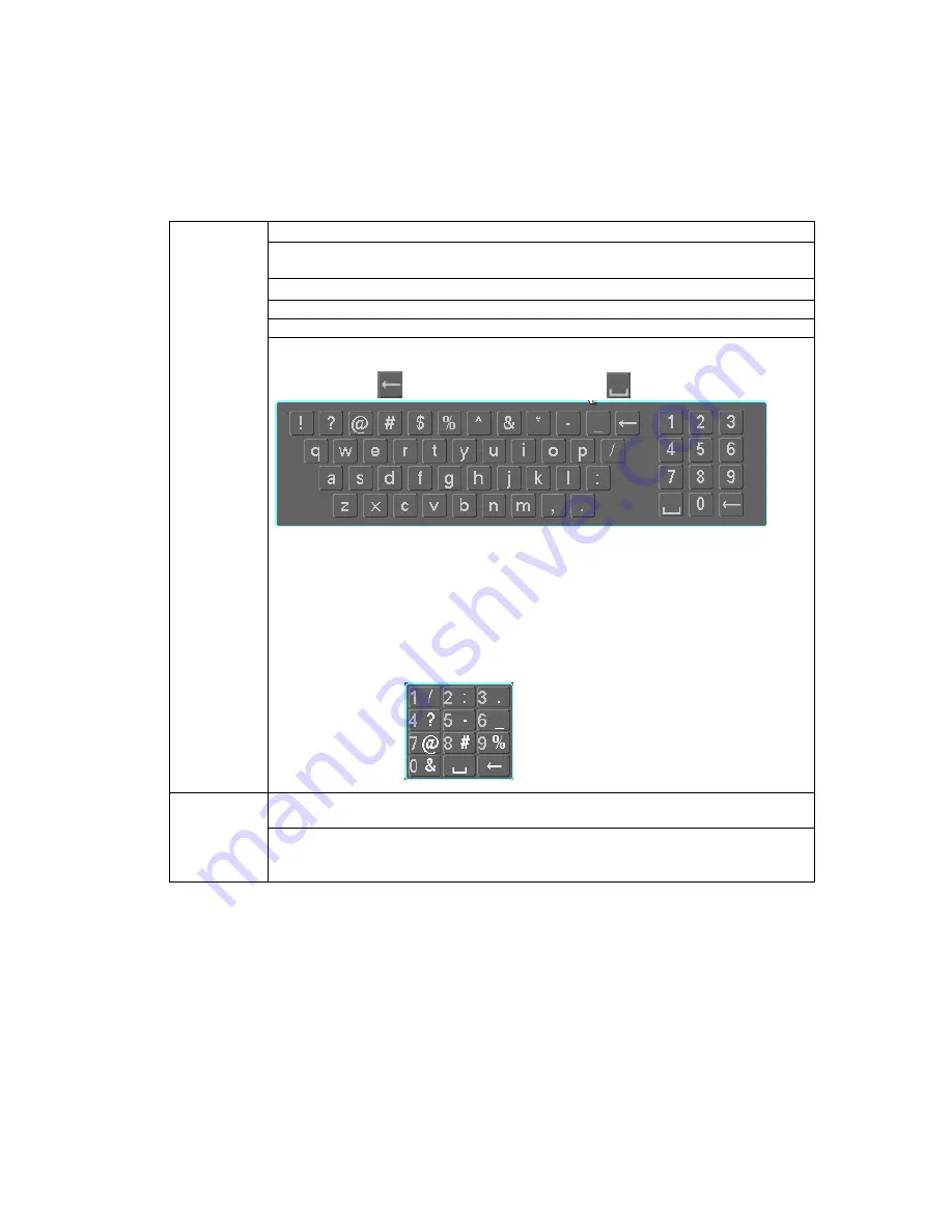
In input box, you can select input methods. Left click the corresponding button
on the panel you can input numeral/English character (small/capitalized) and
symbols. Here
stands for backspace button.
stands for space button.
Click Shift to switch upper/lower cases.
1) In English input mode: _stands for input a backspace
icon and ← stands
for deleting the previous character.
2)
In numeral input mode: _ stands for clear and ← stands for deleting the
previous numeral.
3)
In symbol input mode: _ stands input a backspace icon and ← stands
for deleting the previous symbol.
Double left
click mouse
Implement special control operation such as double clicke item in the file list
to playback the video.
In multiple-window mode, double left clicke channel to view in full screen.
Double left click current video again to go back to previous multiple-window
view.
Summary of Contents for VEC0404HD-M70
Page 1: ...Video Matrix Platform User s Manual V 1 0 0 Dahua Technology CO LTD ...
Page 29: ...24 Figure 3 9 Switch to input device list Please see Figure 3 9 ...
Page 32: ...27 Figure 3 12 Step 2 Click add You will see Figure 3 13 Figure 3 13 ...
Page 65: ...60 Figure 3 54 Buzzer Buzzer rings when motion detection alarms 3 2 4 6 2 Video Loss ...
Page 69: ...64 Display is shown below as in Figure 3 59 Figure 3 60 and Figure 3 61 Figure 3 59 ...
Page 70: ...65 Figure 3 60 ...
Page 83: ...78 Figure 3 80 Click Add to add new Raid Select corresponding level Figure 3 81 ...
Page 91: ...86 Figure 4 7 Hide PTZ Console ...
Page 101: ...96 Figure 4 23 4 2 2 5 Sub Card Status View sub card fan and power status ...
Page 102: ...97 Figure 4 24 4 2 3 System Config 4 2 3 1 General ...
Page 110: ...105 Figure 4 33 4 2 3 8 NTP ...
Page 122: ...117 Figure 4 45 ...
Page 131: ...126 Figure 4 56 Group setting is as follows please see Figure 4 57 and Figure 4 58 ...
Page 137: ...132 Figure 4 65 ...
Page 140: ...135 Figure 4 69 4 2 4 7 Snapshot ...
Page 143: ...138 Figure 4 72 Figure 4 73 ...
Page 149: ...144 Figure 4 82 Step 4 Click Add See Figure 4 83 Figure 4 83 ...


