background image


WEB Operations  

44


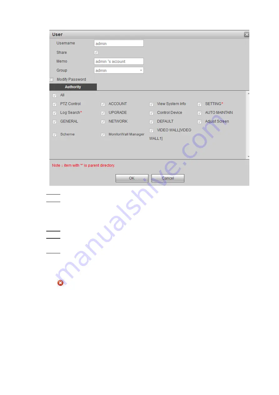
Figure 3-38 Modify user information 


Step 2  Modify user information according to your requirements. 

Step 3  Click 

OK

 to make your modification effective. 

Modifying passwords 

Step 1  Select 

Modify Passwords

Step 2  Enter your old passwords, and then enter your new passwords and conformed the new 

passwords. 

Step 3  Click 

OK

Deleting users 

Click

, you can delete a user. 

3.4.1.2.2 User Group 

In the network, authorities of users can be different. You can put users with the same authorities 

into a group so that you can maintain and manage users’ information more easily. You can also 

increase groups, delete groups, and modify group passwords. 

Select 

SETTING  >  SETTING  >  ACCOUNT  >  Group

,


the

  Group 

interface is displayed. See 

Figure 3-39. You can also increase groups, delete groups, and modify group passwords. For 

details, refer to “3.4.1.2.1 User”. 

Summary of Contents for VI0401HD-DC3000

Page 1: ...Embedded Multi Screen Controller User s Manual V2 0 0...

Page 2: ...n to device especially storage devices For example place the device in a special computer room and cabinet and implement well done access control permission and key management to prevent unauthorized...

Page 3: ...rypted transmission will cause some loss in transmission efficiency 11 Secure Auditing Check online users we suggest that you check online users regularly to see if the device is logged in without aut...

Page 4: ...s the device user or data controller you might collect personal data of other such as face fingerprints car plate number Email address phone number GPS and so on You need to be in compliance with the...

Page 5: ...tions description or errors in print If there is any doubt or dispute please refer to our final explanation Upgrade the reader software or try other mainstream reader software if the Manual in PDF for...

Page 6: ...e Device Operate the device within the rated range of power input and output Do not dissemble the Device Transport use and store the Device under the allowed humidity and temperature conditions Electr...

Page 7: ...Ultra High Definition Capture Card 9 1 6 4 VI0801HH DC3000 Capture Card 10 1 6 5 VI0401HS DC3000 3G SDI Capture Card 10 1 6 6 VO0801HH DS3000 HDMI Output Card 11 1 6 7 VO0401HS DC3000 3G SDI Output C...

Page 8: ...39 3 4 2 Network Setting 50 3 4 3 Event Management 55 3 4 4 Signal Management 55 3 4 5 Display Management 65 3 4 6 Scalability Configuration 82 3 5 Information 83 3 5 1 About the Controller 83 3 5 2...

Page 9: ...rameters Name Description Model Embedded Multi Screen Controller System configuration Main processor Intel X86 Braswell processor Operating methods Controlled by Web interface through browsers Card sl...

Page 10: ...control external matrices and display screens RS 232 One DB 9 port for programs debugging and central control RS 485 One RS 485 port reserved Normal specification Power supply 115V 230V 47Hz 63Hz red...

Page 11: ...e screen And network signals from 32 channels can be displayed Video signals can be copied and one video signal can be displayed on two windows Video signals can be displayed through peer to peer comp...

Page 12: ...TCP UDP RTP and RTSP The Controller can acquire system logs remotely Analog videos and digital videos can be displayed on screens in turn through remote management softwares In addition the Controller...

Page 13: ...troller to factory settings by only pressing one button 1 4 Introducing Boards Table 1 1 About the printed Circuit Boards No Name Mode Categorization Descriptions of interfaces Notes 1 Main device Spl...

Page 14: ...r supply ports and smart temperature controlling fans SeeFigure 1 2 Figure 1 2 Appearance of the main device cabinet The front panel displays the working state of the Controller Table 1 2 Details abou...

Page 15: ...nication input port reserved 6 Voice communication output port 7 Ethernet port 8 Alarm clearance button 9 Two alarm input ports one alarm output port and an RS 485 port reserved 10 RS 232 port for scr...

Page 16: ...saturability Time and titles in OSD channel can be superimposed and positions where they can be superimposed can be configured VI0401HD DVI capture card can see through fogs The indicator keeps on an...

Page 17: ...definition capture card Description There are two HDMI video input ports and these ports can input HDMI signals There are two operating indicators There are two audio loop output ports High speed data...

Page 18: ...ime and titles in OSD channel can be superimposed and positions where they can be superimposed can be configured The indicator keeps on and the port flickers normally 1 6 5 VI0401HS DC3000 3G SDI Capt...

Page 19: ...ight operating indicators High speed data connector includes x4 PCI E gen2 and 12V DC power supply Functions Outputs videos whose resolutions are 1920 1080 60Hz and meet VESA standard Currently only c...

Page 20: ...11 LSC0801HN LED sending card Description There are eight RJ 485 ports and comply to the RGMII standard There are eight operating indicators and eight data indicators High speed data connector includ...

Page 21: ...abinet and check if data cables power lines the connection of the motherboard and port board are loose Information about the Controller like the serial number is written on the label pasted on the sid...

Page 22: ...Unpacking the Box and Wiring 14 2 3 Wiring...

Page 23: ...the corresponding gateway and subnet mask Step 3 Use ping IP address of the Controller to check if the network is correctly connected Step 4 Select Tool Internet Options Custom Level in the IE Browser...

Page 24: ...of 8 to 32 characters specifically the passwords can be the combination of uppercase letters lowercase letters and special characters and are not included The passwords must at least contain two kind...

Page 25: ...17 3 3 Screen Click Screen and then the interface is displayed as follows See Figure 3 3 Figure 3 3 Screen 3 3 1 Adding Screens The first time you log in you need to add screens See Figure 3 4 Figure...

Page 26: ...n the Device Tree or Customization To open the freeform windows click the corresponding signal source in the Device Tree or Customization and then press the left mouse button to draw a rectangle To ma...

Page 27: ...3 1 Table 3 1 Description of the play in order list Parameter Description No Displays the quantity of signal sources and the order of videos played At most 16 signal sources can be added into the pla...

Page 28: ...you can cancel the conference mode Signals played in order Click signals start to be played in order The icon becomes Click signals being played in order will stop Roaming Click the system enters roam...

Page 29: ...plit Click appears Click the windows will be split into patterns like Lock Click you can lock the window the icon turns to After windows are locked you can not adjust their positions and sizes Close C...

Page 30: ...the Scheme interface See Figure 3 7 Figure 3 7 Scheme Step 2 Click Step 3 Click to save the scheme See Figure 3 8 Figure 3 8 The saved scheme Step 4 Reset configurations for the current layout and ta...

Page 31: ...eme tour Click Stop to stop playing video signals with preset schemes When video signals with preset schemes are played actions on the Screen interface can not be conducted The numbers are used to dif...

Page 32: ...r you selected After blocks are split the original open windows will be closed but the original signals will be reserved If the quantity of original open windows is less than the quantity of the block...

Page 33: ...igure 3 14 Block Splitting Window splitting Window splitting means spliting the selected windows according to your requirements Several signals can be displayed in the same window Step 1 Select the wi...

Page 34: ...lit the original signals will be displayed in the first window and No Signal will be displayed in other windows Figure 3 16 Window splitting 3 3 7 Refreshing the Video Wall Click you can refresh the c...

Page 35: ...screens 3 3 9 1 Opening and Closing Screens After you have connected the Controller to serial ports on the screen you can open and close screens You have to connect screens to RJ 45 serial ports on th...

Page 36: ...ines Port 1 or Port 8 should be connected to one of the three RJ 45 serial ports and the other should be connected to the Liquid Crystal Display After you have finished wiring of RJ 45 serial port you...

Page 37: ...ight mode includes energy saving mode standard mode and highlight mode Only certain types of screens have this function Depending on different screen configuration protocols the screen modes you can s...

Page 38: ...can select all blocks Step 3 Slelect a mode according to your requirement 3 3 9 3 Screen Adjustment You can set parameters like brightness and contrast for screens that display DVI and VGA signals Onl...

Page 39: ...ay DVI VGA and Video signals For actual adjustable parameters refer to the real hardwares Click or to adjust parameters 3 3 9 4 Selecting Screen Input Sources You can select input signal source types...

Page 40: ...p 3 Slelect a mode according to your requirement 3 3 9 5 Signal Mode Installation personnel will select corresponding screen signal modes depending on your requirements In some cases the augmented mod...

Page 41: ...virtual LED and OSD overlay set digital zoom set decoding strategies adjust signal parameters and display screen numbers 3 3 10 1 Controlling PTZ You can control rotating directions up down left righ...

Page 42: ...ion and then click and hold the left mouse button the order with of rotating steps and direction is sent to PTZ devices Release the mouse button to stop the PTZ control 3 3 10 2 Virtual LED Select a c...

Page 43: ...six RGB values or you can click the color area to select Type You can set title types For example you can set title types as text or time Display way Set modes for titles to be played on the virtual L...

Page 44: ...haracter spacing range can be 0 5 Font type Used to set typefaces for virtual LED titles and you can set the typefaces as simsun or FZHTFW Font color Used to set colors for the virtual LED titles You...

Page 45: ...click to delete a single virtual LED 3 3 10 3 OSD Overlay You can customize OSD overlay effect for the local signals You need to superimpose items like time titles and channel titles so that they can...

Page 46: ...Digital zoom You can adjust the position and size of image displaying area in windows You can cut images and splice them 3 3 10 5 Decoding You can drag the sliding block to adjust the smoothness of v...

Page 47: ...ightness saturability and equilibrium is 0 100 the range of margin is 50 50 3 3 10 7 Displaying Screen ID Click screen numbers can be displayed on the screen Click the icon again the screen numbers wi...

Page 48: ...ck OK setting is finished If you changed the language the Controller will automatically reboot 3 4 1 1 2 Date Setting Set system date for the Controller and also decide whether to enable Network Time...

Page 49: ...number of the NTP server Interval Update period is the period that the NTP server will be updated Step 3 Click OK and then the setting is finished 3 4 1 2 User Management In the Controller you can ma...

Page 50: ...ords Select SETTING SETTING ACCOUNT User and the ACCOUNT interface is displayed See Figure 3 36 Figure 3 36 Account Add users Adding users into a group and set users authorities The user admin with th...

Page 51: ...recommended that when you are assigning authorities to common users make their authorities not greater than the advanced users Step 3 In Authority select system authority for users Select a checkbox t...

Page 52: ...Step 3 Click OK Deleting users Click you can delete a user 3 4 1 2 2 User Group In the network authorities of users can be different You can put users with the same authorities into a group so that yo...

Page 53: ...ect items that you want to restore to the factory setting Put a tick in the checkbox in front of ALL to select all the items that you want to restore to the factory setting If you have put a tick in t...

Page 54: ...ths to export the configuration file 3 4 1 5 Auto Maintenance You can maintain the system by rebooting and closing the system You can also make the system reboot itself automatically Select SETTING SE...

Page 55: ...p 3 Click Upgrade and then the system will be upgraded There is a progress bar indicating the progress of the upgrade When you click Upgrade a dialogbox will pop up to inform you that you need to make...

Page 56: ...ording to the rotation speed of the fans The Intelligent Temperature Control interface will be displayed The system will start corresponding rotation speed according to different temperature ranges Se...

Page 57: ...ou can download the packet capture files to the Controller and then provide the files for technical personnel to analyze network conditions Select SETTING SETTING FAN CONTROL ASSIST TOOL and the Netwo...

Page 58: ...ork parameters to ensure the Controller can send and receive data to and from other devices 3 4 2 1 TCP IP 3 4 2 1 1 TCP IP Set IP address and DNS server for the Controller according to the network pl...

Page 59: ...WEB Operations 51 Figure 3 49 TCP IP Step 2 Configure parameters For detailed parameters see Table 3 4 Table 3 4 TCP IP parameter Parameter Description...

Page 60: ...put of each network card is basically the same If one network card has malfunctions the other one will work normally When checking your network connection state if the two network cards are both disco...

Page 61: ...UDP port can be set according to your requirement The default port number is 37778 HTTP Port You can set port number of the HTTP port according to your requirement The default number is 80 If you ente...

Page 62: ...rity Select IP devices devices with IP address that can visit the Controller After you have select devices that can visit the Controller you can enable the allowlist function and then only IP devices...

Page 63: ...anagement Set alarm mode for network malfunctions When the Controller has network malfunctions the system will give an alarm Seect SETTING EVENT ALARM and the Net interface is displayed See Figure 3 5...

Page 64: ...terface is displayed See Figure 3 54 Figure 3 54 Analog Matrix 1 Step 2 Click Add The Add interface is displayed See Figure 3 55 Figure 3 55 Add matrices Step 3 Configure parameters For detailed param...

Page 65: ...RS 232 1 COM1 corresponds to RS 232 2 COM2 corresponds to RS 232 3 COM3 corresponds to RS485 Baud rate Serial communication baud rate Odd Even parity Check bits of serial communication Data bits Seri...

Page 66: ...4 1Matrix Step 3 Click Save 3 4 4 1 3 Matrix Protocol Select matrix protocols according to matrix types You can send matrix orders to matrices according to matrix protocols to manage the matrices Ste...

Page 67: ...Interchange ASCIIC Step 4 Click OK and the setting is finished You can add matrix protocols by uploading lua script files that contains matrix protocols 3 4 4 2 Registration After adding remote devic...

Page 68: ...yed on the screen when the network is disconnected Reserved stage the screen reserves the last frame for a period you set and then the screen turns blank Time setting If the reserved state is to reser...

Page 69: ...hat you need to add Manufacturer Keep manufacturers of the devices that you add the same as that of the Controller If you select General in the Manufacture drop down box you connect the devices to the...

Page 70: ...lates to your local PC The template you download is a file in csv format Details the file contains are displayed in Figure 3 62 Figure 3 62 Template information Import You can import network signals i...

Page 71: ...l signals Abnormal mode You need to do abnormal condition management when local signals are disconnected to the network Step 1 Configure abnormal mode according to your requirements For detailed param...

Page 72: ...Root in the Group List and click and then you can set groups under Root Click behind the group name you can modify group names Click to save your modification Click you can add groups in groups Step 3...

Page 73: ...d splicing condition to enable signals to be played on the video walls Select Setting Display Video Wall and the Video Wall interface is displayed See Figure 3 65 At most 16 video walls can be connect...

Page 74: ...WEB Operations 66 Figure 3 66 Layout config Step 2 Enter video wall names and their descriptions Step 3 Click The Video Wall Setup interface is displayed See Figure 3 67...

Page 75: ...output signals Communication port Output serial ports COM1 COM3 Baud rate Serial communication baud rate Odd Even parity Check bits of serial communication Data bit Serial communication data bits Stop...

Page 76: ...input port VGA input port RGB input port Video input port Dahua 5 2 3 0 Samsung 24 20 10 12 Delta Greentech 3 2 5 4 Step 5 Click OK If you select LED_NEW as the device types 960 540 60 as resolution o...

Page 77: ...nding cards See Figure 3 70 Figure 3 70 Setting row and column number of sending cards Step 8 Optional One Ethernet port can be bound with more than one sending cards Connect the sending cards to the...

Page 78: ...ackground picture in the drop down box For methods of uploading background pictures see 3 4 1 7 Background Picture Correction coefficient Select coefficient correction files in the drop down box click...

Page 79: ...Click Send to Hardware to send settings to the LED screen Step 9 Optional Click OK and the setting is finished Step 10Do Step 3 Step 5 again to add more screens Select screens that you want them to be...

Page 80: ...ving cards Select Setting Display Receiving Card Settings and the Receiving Card Settings interface is displayed See Figure 3 73 Figure 3 73 Receiving card settings Modifying parameters of receiving c...

Page 81: ...h of the light board is 1 256 Module height Cabinet width The range of width and length of the current box that carried by receiving cards is 1 256 Cabinet height Visual refresh frequency The rate tha...

Page 82: ...p 6 Click Save and the setting is finished Step 7 Click Send to RecvCards to make your modification effective Data exchange Receiving cards consist of several data sets Data sets present corresponding...

Page 83: ...data set exchange is completed More operations Export configurations Click Export parameters of receiving cards will be exported in the format of Json files Import configurations Click Import you can...

Page 84: ...sated Step 1 Select Setting Display Screen Adjustment The Screen Adjustment interface is displayed See Figure 3 78 Figure 3 78 Screen adjustment Step 2 Click Acquire The RecvCards Selection interface...

Page 85: ...The default bit is 15 bit The grayscale bit is determined by chips used by the screen For details consult technical personnel Image quality Select image quality according to your requirements Image qu...

Page 86: ...all the receiving cards Click Send to Single Wall you can send image parameters to all receiving cards of a single video wall 3 4 5 5 Screen Control You can control images on the screen The operation...

Page 87: ...can control the on off state of a screen corresponding to the output port Click Send to All Walls and then you can control the on off state of all screens Click Send to Single Wall and then you can co...

Page 88: ...testing Step 2 Select self testing types according to your requirements Step 3 Click Send to Output Port you can control a single screen that corresponds to a single output port to make the screen do...

Page 89: ...fficient files to the system 3 4 5 7 Screen Timer Set on off time for each screen Each screen will be on off according to the time that you set Step 1 Select Setting Display Screen Timer The Screen Ti...

Page 90: ...to your requirements See Figure 3 89 Figure 3 89 Preview and monitor Preview and monitor functions can only be enabled on Firefox browser 3 4 6 Scalability Configuration 3 4 6 1 Central Control Settin...

Page 91: ...ication ports Data bits Data bits of communication ports Stop bits Stop bits of communication ports include 1 1 5 and 2 Odd Even Parity Parity bits of serial communication port including N A Odd and E...

Page 92: ...ID resolutions FPS net flow and bit rate See Figure 3 92 Figure 3 92 Decode information 3 5 1 3 About the Controller You can acquire details about the Controller and you can restore the information y...

Page 93: ...e displayed in the list Click you can save files in your local conmputer or USB flash drive Click you can rename files Click you can delete files 3 5 1 4 Controller State You can view the state of the...

Page 94: ...ure 3 95 Figure 3 95 System logs Step 2 Enter start time and end time Step 3 Select log types Step 4 Click Search Click Backup and you can store the logs in your local PC Click Clear you can delete al...

Page 95: ...SION you can see details about the versions of the Controller 3 5 2 Help Select INFO HELP INFO USER S MANUAL you can check or download the user manual 3 6 Exit Log off the current user next time you w...

Page 96: ...oller remotely through Digital Surveillance System DSS For details about DSS refer to user manual of DSS For details about the eight fine pixel LEDs receiving card and create new video walls through D...

Page 97: ...single channel several channels or all channels can not output videos A It might be The program and front end devices of a third platform are incompatible Video sources have malfunctions Hardware of t...

Page 98: ...might occur Short circuit must be prevented when connecting the external wires Only when all wires are connected can you connect the Controller to the power supply When all wires are connected bind al...

Page 99: ...S 485 otherwise these ports might be damaged Make sure that the Controller is away from high temperature heat sources Make sure that the Controller is horizontally and stably installed And make sure t...

Reviews: