GB
5.5
Electronic board
It serves for regulation of wirefeeding motor and wire speed.
5.6
Wirefeeding mechanism with motor
It is compact-designed, direct-circuit motor. The mechanism is feeding the wire ttrough the wire
feeding roller, which is placed on reductor's shaft. The strength of pressure-roll to the wire and the
feeding roller may be adjustable by turning the screw (with spring).
5.7
Magnetic valve -
It serves to open and close the gas outlet from the cylinder. From there the gas goes trough the
seamed tube into the welding cable and torch. The gas flow is active by pressing the button on torch
only.
5.8
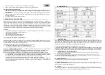
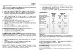
Control and serve elements
main switch
switch for current selection (separated from main switch at Varmig 1905c only)
wirefeeding velocity-adjustment knob
connection cable
mass cable with clamp
welding cable with torch
gas-pressure regulator
6. PREPARING FOR WELDING
6.1. Mains connection
VARMIG VARMIG 1600c: Welding machines are equipped with connection cable and standard plug for
230 V / 50 Hz. They are appropriate for connection to each plug socket with protecting contacts.
VARMIG 1905c welding machines are equipped with connection for 1 x 400V/50Hz and 230V/50Hz. At
connection to 230 V mains supply use the appropriate adapter enclosed.
Please assure, that the main switch is in position
0
before connecting the cable to the plug
socket.
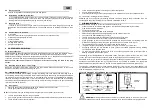
6.2 Mounting the wire spool
– small (5 kgs)
Mount the wire-spool (low alloyed steel) onto the spool holder. Please pay attention to the correct
direction of unwinding the wire by mounting the spool.
6.3 Leading-trough the wire
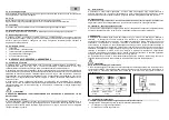
The wire has to be bend before leading it trough the feeding rollers and infeed tube of welding torch to
avoid sticking. With turning the screw to the left release the spring and shift up the clamping handle with
the braking-roller. Assure, that the groove on the feeding-roller is equal to the welding wire diameter.
Insert the wire trough the infeed tube of the roller drive and a few cm into the infeed tube of the welding
torch. Adjust the appropriate pressure of the feeding roller with turning the srew to the right (the feeding
roller may not slide on the wire).
6.4 Gas cylinder
place the gas-cylinder onto the backside of the machine (max 10 kgs) or floor
fix the gas-cylinder in place with safety chain
N.B.!
The cylinder will only be optimaly fixed in the upper part of the cylinder (not at the neck)
remove the protective cap from the gas cylinder
give the gas-cylinder valve a brief turn to the left (anticlockwise) to blow off any dirt around the valve
check the seal on the pressure regulator
screw the pressure regulator onto vthe gas cylinder and tighten it
assure, that no gas deserts
attach the protective-gas hose to the gas-pipe on the machine and fix it with enclosed embrance
6.4.1. Additional
– welding with flux cored wire
Shielding gas is not neccessary for welding with flux cored wire, the wire itself is sufficient. Also, it is
neccessary to use proper welding torch for example TORCH RV 13/2m P.
7. MIG/MAG WELDING
Caution!
Before starting up for the first time read the safety rules.
place the machine onto the working place so, that the best cooling possibility is achieved
plug the machine into the mains
set the protective-gas rate
connect the earth (mass) cable to the workpiece
adjust the wirespeed with a knob aproximately into the middle of the scale
check out if the wireis leaded-trogh correctly
remove the protective gas-nozzle and the contact nozzle from the torch
assure, that the chosen contact nozzle is equal to the wire diameter
press the button on the torch and check the wirefeed and the gas outflow. If everything is OK, the
wirefeeder is pushing-out the wire and the gas valve is open, so the das is coming out
fix the protective gas-nozzle and the contact nozzle back to the torch
the perfect length of the welding wire outside the nozzle is 5-10 mm (cut off the rest)
depending materials you are intended to weld, choose the suitable parameters with a welding
current-switch and wirespeed-knob
try to weld by pressing the button on the torch. If the chosen parameters are correct the sound of
welding is equable and the seam is well.
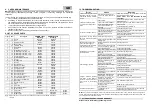
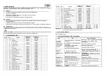
The welding current is adjustable with a 4 position switch. Turn right
– higher current / turn left – lower
current. The value of the selected current is marked on the front panel for each switch-position.
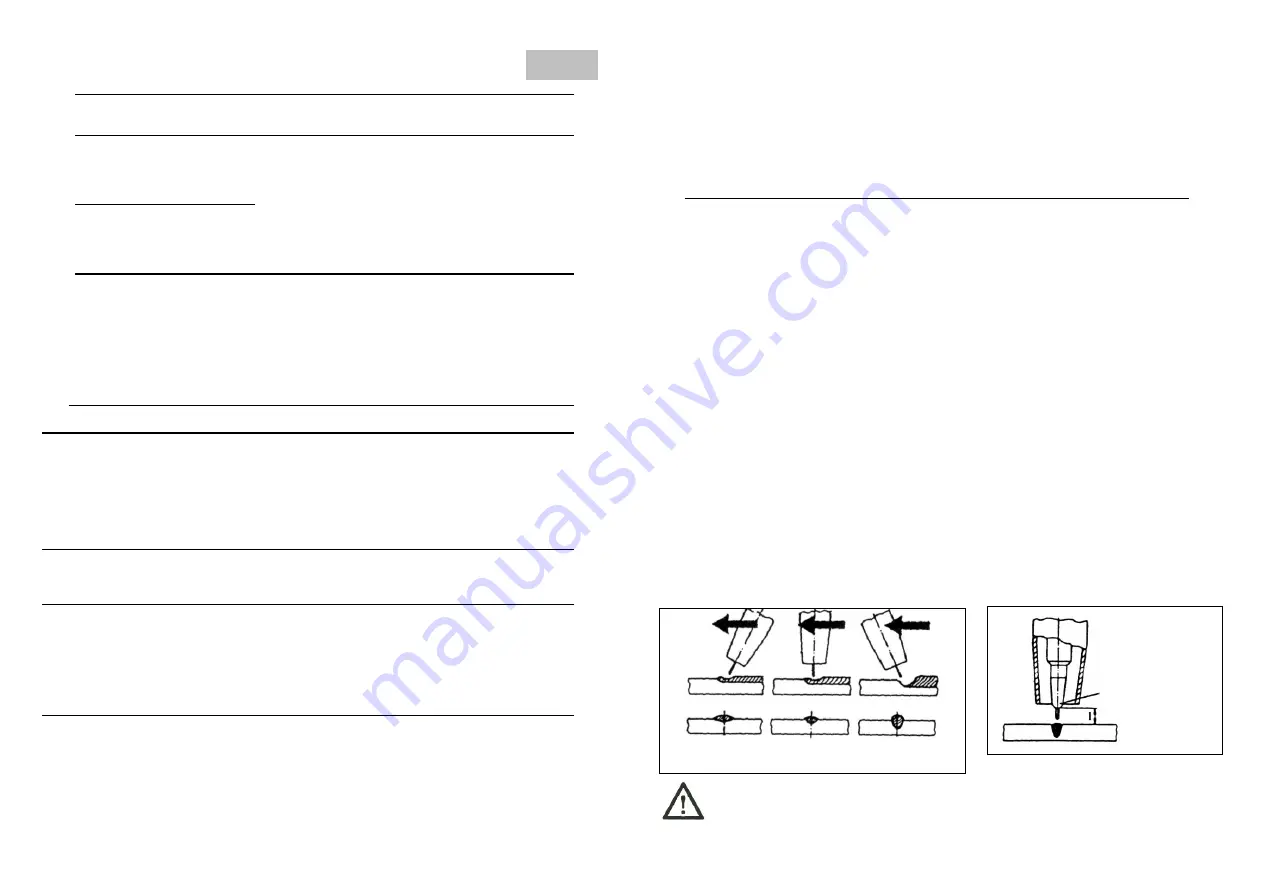
The stable arc is very important for quality welding-seam. Please pay attention to the constant distance
beetwen nozzle and workpiece and try to guide the torch as constatly as possible. The appropriate
distance between torch and workpiece is around 5-10 mm (stainless steel) and 20 mm (aluminium).
The machine is equipped with an overtemperature thermostat. If this is active, the orange indicator is lit
up. At that moment the machine is out of order. The cooling system operates only. Tha machine will fail to
weld until temperature indicaror is lit up.
Caution! DON'T SHUT OFF THE MACHINE IF TEMPERATURE INDICATOR IS LIT UP!
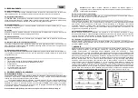
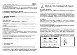
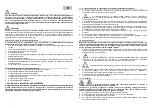
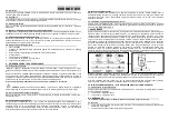
CONTACT
NOZZLE
PUSH RECTANGULAR PULL
POSITION POSITION POSITION
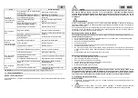
WARNING!
Welding cable and mass cable are connected directly to the power part of the
machine. Please assure, that the torch and mass clamp are not in short-circuit before turning the switch.


