3.2 Operation Switch Design
3-2
3.2 Operation Switch Design
3.2.1 Basic operations for operation switch design
Described below is the method used to lay out the operation switches on the interface panel screens after designing
each of them.
The setting screen will differ slightly depending on the type of operation switch concerned. A description of individual
operation switches is given for each type of switch on the following pages.
1
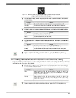
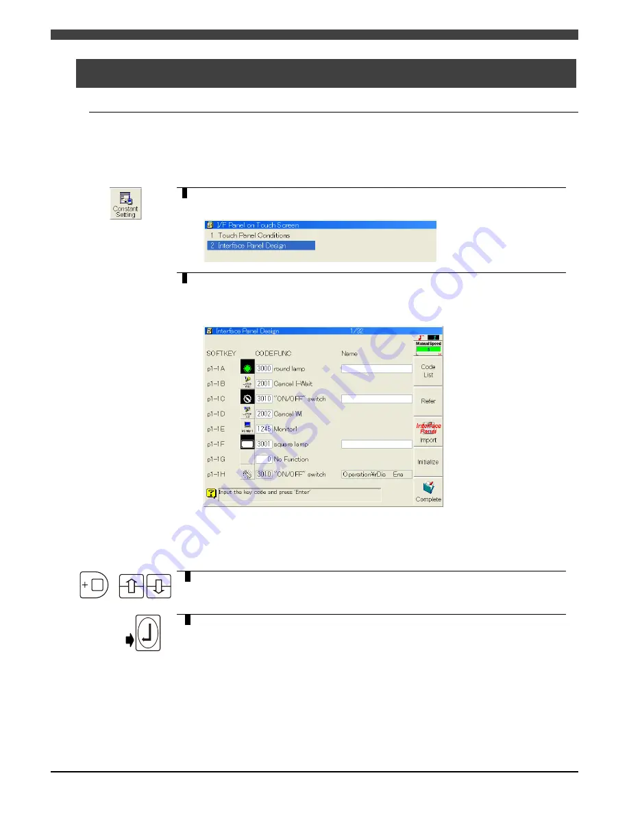
Select <Constant Setting> in the teach mode.
Select [22 I/F Panel on Touch Screen] from the menu which is displayed.
>> The interface panel constants menu such as the one shown below appears.
2
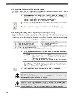
Select [2 Interface Panel Design].
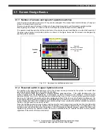
>> The operation switch design screen (list screen) such as the one shown below
appears. (The example displayed shows the statuses already established upon
completion of some of the settings. All the keys are set to "No Function" at the
default setting.)
At the far left, the layout numbers of the keys are indicated as a combination of the page
number and position number, and to the right of these numbers are indicated the
external appearance of the keys, their names and other important information.
Detailed settings are not displayed on this screen.
+
3
Using the [ENABLE] and [Up] or [Down] cursor keys, it is possible to switch the
list from the switch located at the top left of screen page 1 (P1-1A) to the switch
positioned at the bottom right of screen page 8 (P8-4H).
Number
4
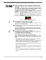
First, align the cursor with "CODE", and input a number to indicate the type of
operation switch (lamp, push button switch or function key) to be laid out at the
position concerned.
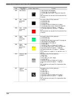
Refer to Table 3.2.2 List of operation switch keys for the code numbers which
are to be input.
If "0" is input, the corresponding switch has no function (only a gray background
appears).
>> When a number is input, its title is displayed in the "Function" field on the right.

