Important Note
Service Form SF99006 and an isometric sketch of the Remote Piping Layout showing pipe size, location of fittings, measured lengths, and
elevations MUST BE SUBMITTED TO Daikin McQuay Technical Response Center and reviewed at least two weeks prior to beginning piping
installation. McQuay Factory Service will not perform startup without reviewed Service Form SF99006 and drawing. Installation must match
reviewed drawing.
All field piping, wiring and procedures must comply with design guidelines set forth in the Remote Evaporator section of product literature, and be
performed in accordance with ASHRAE, EPA, local codes and industry standards. Any product failure caused or contributed to by failure to comply
with appropriate design guidelines will not be covered by manufacturer's warranty. Daikin McQuay Technical Response: Fax: 763-509-7666
Phone : 540-248-9201; E-mail: techresponse@mcquay.com
116
IM 1167
Remote Evaporators
Remote Evaporator Refrigerant Piping
Careful design of refrigerant piping is necessary for proper
system operation. Design the refrigerant piping to accomplish
the following:
1
Assure proper refrigerant feed to the evaporator.
2
Provide practical and economical refrigerant line sizes
without excess pressure drop.
3
Maintain uniform oil return to the compressor under all
load conditions.
4
Refer to the latest version of the ASHRAE Handbook for
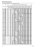
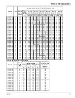
recommended piping practice; use included tables for
correct pipe sizing.
5
Keep the refrigerant suction line pressure drop to a
maximum of 2 F. in saturated temperature equivalent.
6
Each suction line's velocity must be sufficient to carry oil
considering a 25% capacity reduction in each circuit.
7
When facing the unit control box, the left-hand
compressor is circuit # 1, and the right-hand is circuit #
2. If present, the compressor behind #2, on the right-hand
side, is circuit #3.
8
Liquid lines may be insulated to prevent collection of
condensation, if needed.
The following applies to all size units:
•
Maximum linear line length cannot exceed 75 feet
•
Maximum total equivalent length (TEL) cannot exceed 180
feet (75 feet for vertical suction lines)
•
The evaporator cannot be located more than 20 feet above or
30 feet below the outdoor unit.
•
Suction line connection at unit = 4 1/8-inch OD each
•
Underground refrigerant piping is not permitted
•
Field piping must include adequate service taps for checking
filter-drier, subcooling, and superheat.
•
Insulate complete suction lines. Liquid lines may be
insulated to prevent collection of condensation if required.
Table 94: Fitting Equivalent Feet of Pipe
Line Size
In. OD
Angle Valve
Globe
Valve
90-Degree
Std. Radius
Elbow
90-Degree
Long Radius
Elbow
2 5/8
29.00
69.0
6.0
4.1
3 1/8
35.0
84.0
7.5
5.0
3 5/8
41.0
100.0
9.0
5.9
4 1/8
47.0
120.0
10.0
6.7
5 1/8
58
140
13
8.2
Note: TEL values for the filter-drier and solenoid valve are already included
and should not be added to the liquid line drop.
Piping Layout
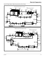
Figure 55
shows the piping layout for one of the two or three
refrigerant circuits for AWS units with a remote evaporator.
The outdoor unit, the evaporator, and a kit of refrigerant
components are shipped as separate pieces for field mounting,
wiring, and piping. The suction shutoff valve is standard on
remote evaporator units. Note: Field insulation of the suction
lines and the liquid line on circuits with economizers is
required. The outdoor unit will have a refrigerant charge equal
to that of a packaged unit pumped down into the condenser.
The additional charge of refrigerant and oil required by the
field piping is supplied and installed by the customer. The
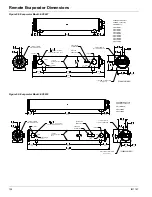
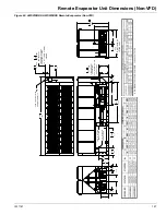
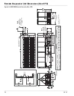
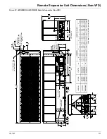
location and size of the refrigerant connections are shown on
the dimension drawings beginning on
page 126
.

