background image

IM 1167 

39

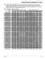
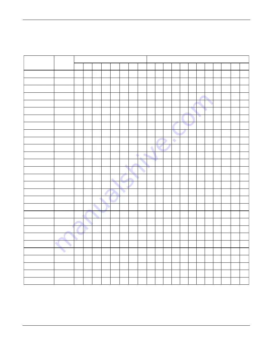
Lifting & Mounting Weights (I-P Units)

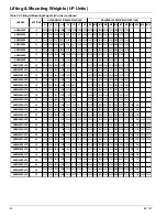
Lifting & Mounting Weights (I-P Units)

Note: 

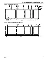
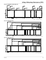
Lifting and Mounting Locations begin on 

page 43

. See Physical Data tables, beginning on 

page 43

 for Shipping and 

Operating weights, and weight adjustments for accessories and options. All drawings and weights in this manual are 

applicable to AWS B-vintage (Rev 0B) models only. For drawings and information related to (Rev 00) models, consult CAT 

600-6. To determine if your unit is Rev 00 or Rev 0A, check Item 62 of the Item Summary Report for your unit. If you have 

additional questions, contact your Daikin McQuay representative. 

Table 34: Lifting & Mounting Weights (IP units) 

L1

L2

L3

L4

L5

L6

L7

L8

M1

M2

M3

M4

M5

M6

M7

M8

M9

M10 M11 M12

-

-

-

-

-

-

-

-

-

-

-

-

-

-

-

-

-

-

-

-

-

-

-

-

-

-

-

-

-

-

-

-

-

-

-

-

-

-

-

-

-

-

-

-

-

-

-

-

-

-

-

-

3769

MOUNTING LOADS FOR EACH POINT (LBS)

-

-

-

-

-

-

-

-

3735 2918

1595

2892 2264 2243 1609

3364 3333 2988 2961 4096 4059

2208 1793 1745

AWS500BTH 

28

3886 3850 3716 3683

3653 3457 3364 2685 2612 2270

3469 3166 3081 2760 2686 3754

AWS475BTH 

26

3758 3656 3566

2490 2468 1997 1979 1431 1418

2440 2417 3762 3727 3408 3377

925

AWS450BTH 

24

3653 3620 3405 3374 2888 2862

3150 2141 2131 1556 1549 929

2596 1961 1952 3564 3548 3165

-

-

AWS410BDH 

24

3314 3299 3037 3023 2608

3263 3249 2394 2384 1701 1694

2414 2403 1897 1888 3598 3581

1317

-

-

AWS390BDH 

22

3275 3260 2937 2924

3462 3080 3080 2363 2363 1317

3014 1950 1950 1230 1230 3462

AWS350BDH 

20

3594 3594 3014

2337 2253 1369 1320

-

-

1272 1226 3355 3235 3001 2893

-

AWS330BDH 

20

3473 3349 2934 2828 1942 1873

2711 1786 1786 1028 1028

-

1701 1075 1075 3206 3206 2711

-

-

AWS300BDH 

16

3065 3065 2455 2455 1701

2711 2711 1786 1786 1028 1028

1701 1701 1075 1075 3206 3206

808

-

-

AWS280BDH 

16

3065 3065 2455 2455

3160 2554 2542 1391 1385 811

3485

-

-

-

-

3175

AWS250BDH 

14

4158 4139 3501

1380 1301 821 774

-

-

-

-

3103 2924 2503 2359

-

AWS230BDH 

14

4052 3818 3476 3276

-

-

2373 1722 1714

-

-

-

-

-

-

2737 2724 2383

AWS210BDH 

12

3892 3875 2678 2665

-

1572

3202 3116 4317 4200

1530

4005 3896 3194 3108 2426 2360

1433

AWS530BTH 

30

4071 3961 3921 3815 3610 3512

3845 3069 3041 2300 2279 1446

3413 2985 2958 4193 4155 3881

1517 1503

AWS550BTS 

30

3963 3927 3794 3760 3444

3782 3748 2889 2863 2203 2183

3305 3275 2859 2833 4125 4088

2118 1529 1516

AWS525BTS 

28

3925 3890 3724 3690

3994 3651 3618 2666 2642 2137

3695 3097 3069 2455 2432 4030

2079 2060 1488 1474

AWS500BTS 

26

4032 3995 3728

3921 3885 3552 3520 2594 2570

1182

24

3816 3782 3556 3524 3014 2987 2544 2521

3635 2473 2496 1867 1884 1171

2828 2131 2151 4036 4073 3602

-

-

AWS450BTS 

24

3945 3982 3574 3607 2802

3500 3468 2880 2854 2403 2382

2618 2594 1994 1976 3738 3705

2318

-

-

AWS425BTS 

22

3795 3760 3413 3382

3668 3380 3427 2762 2800 2286

3334 2506 2541 1893 1919 3618

1166 1166

-

-

AWS400BTS 

22

3664 3715 3288

3434 3434 3030 3030 2272 2272

-

20

3567 3567 2960 2960 1847 1847 1094 1094

3030 2272 2272 1166 1166

-

1847 1094 1094 3434 3434 3030

-

-

AWS350BDS 

20

3567 3567 2960 2960 1847

2950 2936 1769 1761 803 799

1679 1672 862

858 3580 3563

807

-

-

AWS310BDS 

16

3461 3446 2664 2652

3333 2862 2760 1749 1686 837

-

3330 3211 2583 2490 1659 1599 892

860 3457

3175 2519 2508 1264 1258 638

3118

-

-

-

-

3190

AWS260BDS 

14

4207 4188 3132

1264 1258 638 635

-

-

-

-

3190 3175 2519 2508

14

4207

-

4188 3132 3118

-

-

-

1498

-

-

3121 3106 2558 2547 1505

4364 4345 2547 2536

-

-

2498 2387 1548 1479

-

-

-

-

-

-

3005 2871

12

4214 4026 2560 2445

1422 1415

-

-

-

-

-

-

2805 2792 2324 2313

LIFTING WEIGHT FOR EACH POINT (LBS)

AWS190BDS 

10

3921 3903 2358 2347

-

-

AWS470BTS 

AWS250BDS 

# OF FANS

AWS225BDS 

12

16

AWS210BDS 

UNIT SIZE

AWS290BDS 

AWS375BDS 

-

-

635

-

Summary of Contents for AWS210BDS

Page 1: ...hillers Group Chillers Part Number IM 1167 REV 00 Date December 2012 2012 McQuay International Model AWS B Rev 0B Standard High Premium Efficiencies Includes models with VFD and models with Remote Eva...

Page 2: ...4 Remote Evaporator Lifting Mounting Locations 158 Remote Evaporator Physical Data 166 Troubleshooting Chart 181 Hazard Identification DANGER Dangers indicate a hazardous situation which will result i...

Page 3: ...S or high efficiency BDH or premium efficiency BDP A high ambient option is required for operation in ambient temperatures above 100 F 37 8 C and up to 125 F 51 7 C and when the VFD low ambient option...

Page 4: ...e to the condenser coils or unit cabinet see Figure 2 Location Locate the unit outdoors and carefully to provide proper airflow to the condenser See Figure 4 page 5 for required clearances Using less...

Page 5: ...on the chiller Alarm Limit Extension Module MicroTech III Main Controller Optional 115V Outlet Cir 1 2 Fan Control Extension Module Controller Fuse Emergency Switch Relay Control Circuit Breaker Unit...

Page 6: ...mesh strainer at evaporator inlet Figure 6 Refrigerant Diagram All High and PremiumEfficiency Models one circuit shown of two three possible circuits AWS PACKAGE CHILLER WITH ECONOMIZER 331994701 REV...

Page 7: ...ing at reduced capacity rather than allowing a shut off on high discharge pressure Building Case 1 Building or Wall on One Side of One Unit The existence of a screening wall or the wall of a building...

Page 8: ...0 6 1 8 8 2 4 10 3 0 12 3 6 Distance Between Units in ft m Capacity Reduction Full Load Power Adjustment Factor 0 00 0 50 1 00 1 50 2 00 2 50 3 00 6 1 8 8 2 4 10 3 0 12 3 6 Distance Between Units in f...

Page 9: ...4 feet and 20 feet to equal 12 feet 1 meter and 5 meters to equal 3 meters Figure 10 Open Screening Walls Adjustment Factors Wall Free Area vs Distance 0 00 2 00 4 00 6 00 8 00 0 10 20 30 40 50 Ope n...

Page 10: ...f glycol is large or if propylene is employed in lieu of ethylene glycol the added pressure drop and loss of performance could be substantial 10 Do not use PVC or CPVC piping due to incompatibility wi...

Page 11: ...ing load the minimum chiller plant capacity during the low load period and the desired cycle time for the compressors Assuming that there are no sudden load changes and that the chiller plant has reas...

Page 12: ...n the expected lowest ambient temperature Inhibitor levels should be adjusted for solutions less than 25 glycol Note Glycol of less than 25 concentration is not recommended because of the potential fo...

Page 13: ...in the chiller evaporator The type and handling of glycol used must be consistent with local codes Performance Adjustment Factors AWS chiller units are designed to operate with leaving chilled fluid t...

Page 14: ...p in sizing the disconnect Terminals are provided in a unit control panel for optional field hookup of the control circuit to a separate fused 115 volt power supply in lieu of the standard factory ins...

Page 15: ...er of Fans per Circuit Fan Diameter 31 5 in 800 mm Fan Motor hp kW Fan Motor RPM Fan Tip Speed fpm m s Airflow cfm l s EVAPORATOR DIRECT EXPANSION SHELL AND TUBE Shell Dia Tube Length in mm Water Volu...

Page 16: ...per Circuit Fan Diameter 31 5 in 800 mm Fan Motor hp kW Fan Motor RPM Fan Tip Speed fpm m s Airflow cfm l s EVAPORATOR DIRECT EXPANSION SHELL AND TUBE Shell Dia Tube Length in mm Water Volume gallons...

Page 17: ...uit Fan Diameter 31 5 in 800 mm Fan Motor hp kW Fan Motor RPM Fan Tip Speed fpm m s Airflow cfm l s EVAPORATOR DIRECT EXPANSION SHELL AND TUBE Shell Dia Tube Length in mm Water Volume gallons liters V...

Page 18: ...er Inch 3 16 3 16 3 16 3 16 3 16 3 16 CONDENSER FANS DIRECT DRIVEPROPELLER TYPE Number of Fans per Circuit Fan Diameter 31 5 in 800 mm Fan Motor hp kW Fan Motor RPM Fan Tip Speed fpm m s Airflow cfm l...

Page 19: ...3 16 3 16 3 16 3 16 3 16 3 16 CONDENSER FANS DIRECT DRIVE PROPELLER TYPE Number of Fans per Circuit Fan Diameter 31 5 in 800 mm Fan Motor hp kW Fan Motor RPM Fan Tip Speed fpm m s Airflow cfm l s EVA...

Page 20: ...16 3 16 3 16 3 16 3 16 3 16 CONDENSER FANS DIRECT DRIVE PROPELLER TYPE Number of Fans per Circuit Fan Diameter 31 5 in 800 mm Fan Motor hp kW Fan Motor RPM Fan Tip Speed fpm m s Airflow cfm l s EVAPO...

Page 21: ...8 246 1 22 8 Rows Deep Fins Per Inch 3 16 3 16 3 16 CONDENSER FANS DIRECT DRIVEPROPELLER TYPE Number of Fans per Circuit Fan Diameter 31 5 in 800 mm Fan Motor hp kW Fan Motor RPM Fan Tip Speed fpm m s...

Page 22: ...e Length in mm Water Volume gallons liters Victaulic inlet outlet conn in mm Max Water Pressure psi kPa Max Refrigerant Press psi kPa BASIC DATA COMPRESSORS SCREW SEMI HERMETIC CONDENSERS HIGHEFFICIEN...

Page 23: ...ngth in mm Water Volume gallons liters Victaulic inlet outlet conn in mm Max Water Pressure psi kPa Max Refrigerant Press psi kPa BASIC DATA COMPRESSORS SCREW SEMI HERMETIC CONDENSERS HIGHEFFICIENCY F...

Page 24: ...Water Volume gallons liters Victaulic inlet outlet conn in mm Max Water Pressure psi kPa Max Refrigerant Press psi kPa 100 377 100 377 20 x 108 508 x 2750 Data AWS350BDH AWS390BDH AWS410BDH 348 1 1224...

Page 25: ...m Fan Motor hp kW Fan Motor RPM Fan Tip Speed fpm m s Airflow cfm l s Shell Dia Tube Length in mm Water Volume gallons liters Victaulic inlet outlet conn in mm Max Water Pressure psi kPa Max Refrigera...

Page 26: ...3 16 3 16 3 16 3 16 3 16 3 16 CONDENSER FANS DIRECT DRIVEPROPELLER TYPE Number of Fans per Circuit Fan Diameter 31 5 in 800 mm Fan Motor hp kW Fan Motor RPM Fan Tip Speed fpm m s Airflow cfm l s EVAP...

Page 27: ...Length in mm Water Volume gallons liters Victaulic inlet outlet conn in mm Max Water Pressure psi kPa Max Refrigerant Press psi kPa BASIC DATA COMPRESSORS SCREW SEMI HERMETIC CONDENSERS HIGHEFFICIENCY...

Page 28: ...Water Volume gallons liters Victaulic inlet outlet conn in mm Max Water Pressure psi kPa Max Refrigerant Press psi kPa 152 1048 152 1048 152 1048 325 2241 325 2241 325 2241 276 1043 259 979 259 979 10...

Page 29: ...ep Fins Per Inch 3 16 3 16 CONDENSER FANS DIRECT DRIVEPROPELLER TYPE Number of Fans per Circuit Fan Diameter 31 5 in 800 mm Fan Motor hp kW Fan Motor RPM Fan Tip Speed fpm m s Airflow cfm l s EVAPORAT...

Page 30: ...me gallons liters Victaulic inlet outlet conn in mm Max Water Pressure psi kPa Max Refrigerant Press psi kPa 268 x 88 x 100 268 x 88 x 100 268 x 88 x 100 6803 x 2225 x 2548 6803 x 2225 x 2548 6803 x 2...

Page 31: ...ns liters Victaulic inlet outlet conn in m m M ax Water Pressure psi kPa M ax Refrigerant Press psi kPa 6 168 325 2241 325 2241 325 2241 152 1048 152 1048 152 1048 133020 62778 155190 73241 155190 732...

Page 32: ...ictaulic inlet outlet conn in mm Max Water Pressure psi kPa Max Refrigerant Press psi kPa 152 1048 325 2241 8 219 152 1048 325 2241 177360 83704 107 403 1 4 1 05 177360 83704 221700 104630 6984 35 698...

Page 33: ...inlet outlet conn in mm M ax Water Pressure psi kPa Max Refrigerant Press psi kPa 325 2241 325 2241 325 2241 152 1048 152 1048 152 1048 8 219 8 219 8 219 6984 35 20 x 108 508 x 2750 20 x 108 508 x 275...

Page 34: ...n Tip Speed fpm m s Airflow cfm l s Shell Dia Tube Length in mm Water Volume gallons liters Victaulic inlet outlet conn in mm Max Water Pressure psi kPa Max Refrigerant Press psi kPa 325 2241 325 2241...

Page 35: ...RFANS DIRECT DRIVEPROPELLERTYPE Number of Fans per Circuit Fan Diameter 31 5 in 800 mm Fan Motor hp kW Fan Motor RPM Fan Tip Speed fpm m s Airflow cfm l s EVAPORATOR DIRECT EXPANSIONSHELL ANDTUBE Shel...

Page 36: ...Victaulic inlet outlet conn in mm Max Water Pressure psi kPa Max Refrigerant Press psi kPa 325 2241 325 2241 152 1048 158 599 158 599 8 2199 8 219 10 273 EVAPORATOR DIRECT EXPANSION SHELL AND TUBE 20...

Page 37: ...lic inlet outlet conn in mm Max Water Pressure psi kPa Max Refrigerant Press psi kPa 276 1043 325 2241 152 1048 26 x 154 660 x 3900 26 x 154 660 x 3900 10 273 10 273 10 273 221700 104630 243870 115093...

Page 38: ...IRECT DRIVEPROPELLER TYPE Number of Fans per Circuit Fan Diameter 31 5 in 800 mm Fan Motor hp kW Fan Motor RPM Fan Tip Speed fpm m s Airflow cfm l s EVAPORATOR DIRECT EXPANSION SHELL AND TUBE Shell Di...

Page 39: ...08 AWS280BDH 16 3065 3065 2455 2455 3160 2554 2542 1391 1385 811 3485 3175 AWS250BDH 14 4158 4139 3501 1380 1301 821 774 3103 2924 2503 2359 AWS230BDH 14 4052 3818 3476 3276 2373 1722 1714 2737 2724 2...

Page 40: ...00BTHVFD 28 4180 4197 3882 3898 3394 3408 2874 2885 2869 2880 2791 2802 2690 2701 2428 2438 2226 2235 2025 2033 AWS530BTHVFD 30 4380 4323 4096 4042 3629 3581 3018 2979 3084 3043 2995 2956 2880 2843 25...

Page 41: ...144 1779 1114 1103 1828 1812 669 AWS500BTS 60 26 1829 1812 969 961 694 688 1656 1641 1209 1198 1764 1689 1674 1499 AWS525BTS 60 28 1780 990 688 1854 1715 1700 1310 1721 1706 1562 1548 1299 999 1486 12...

Page 42: ...AWS500BTHVFD 60 28 1896 1904 1761 1768 1540 1546 1303 1309 1301 1307 1266 1271 1220 1225 1101 1106 1010 1014 918 922 AWS530BTHVFD 60 30 1987 1961 1858 1833 1646 1624 1369 1351 1399 1380 1359 1341 1307...

Page 43: ...e 48 AWS470BTS Standard 24 Figure 23 page 48 AWS475BTH High 26 Figure 24 page 49 AWS500BTS Standard 26 Figure 24 page 49 AWS500BTH High 28 Figure 25 page 49 AWS525BTS Standard 28 Figure 25 page 49 AWS...

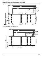
Page 44: ...00 87 6 2225 193 3 4910 7 5 190 3 9 100 17 0 431 188 6 4791 CONTROL BOX L1 M1 M3 L3 M5 L2 M2 M4 L4 M6 AWS 10 FAN DIM DWG 331426601C020A Figure 15 AWS210BDS H AWS225BDS non VFD 229 1 5820 23 6 600 82 7...

Page 45: ...431 188 6 4791 CONTROL BOX L1 M1 M3 L3 M5 M7 L2 M2 M4 L4 M6 M8 AWS 14 FAN DIM DWG 331426603C020A Figure 17 AWS240BDP AWS280BDH AWS290BDS AWS300BDH AWS310BDS non VFD 300 0 7620 23 6 600 82 7 2100 283...

Page 46: ...4791 294 6 7484 CONTROL BOX L1 M1 M3 L3 L5 M5 M7 L7 L2 M2 M4 L4 L6 M6 M8 L8 AWS 18 FAN DIM DWG 331426605C020A Figure 19 AWS310BDP AWS330BDH P AWS350BDS H AWS375BDS non VFD 370 9 9421 23 6 600 82 7 21...

Page 47: ...2381 212 6 5401 330 1 8384 CONTROL BOX L1 M1 M3 L3 L5 M5 M7 L7 L2 M2 M4 L4 L6 M6 M8 L8 AWS 22 FAN DIM DWG 331426607C020A Figure 21 AWS400BTS AWS425BTS non VFD 422 0 10718 23 6 600 82 7 2100 236 2 600...

Page 48: ...2 6 5401 392 2 9962 CONTROL BOX L1 M1 M3 L3 L5 M5 M7 L7 M9 L2 M2 M4 L4 L6 M6 M8 L8 M10 AWS 24 FAN DIM DWG 331426608C020A Figure 23 AWS450BTS H AWS470BTS non VFD 457 5 11620 23 6 600 82 7 2100 236 2 60...

Page 49: ...WS525BTS non VFD 528 4 13420 23 6 600 82 7 2100 236 2 6000 472 4 12000 87 6 2225 2 6 66 7 5 190 3 9 100 354 3 9000 17 0 431 93 7 2381 253 4 6436 423 6 10761 CONTROL BOX L1 L3 L4 L2 L6 L5 L7 L8 M1 M3 M...

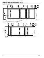
Page 50: ...3638 200 3 5089 205 0 5208 240 9 6118 87 6 2225 7 5 190 3 9 100 2 6 66 750 TYP 19 CONTROL BOX L1 M1 M3 L3 M5 L5 M7 BOTTOMVIEW Figure 28 AWS190BDS AWS200BDS AWS210BDH VFD 333687302 AWS B 0BWITHVFD12FA...

Page 51: ...2225 7 5 190 3 9 100 2 6 66 750 TYP 19 CONTROL BOX L1 M1 M3 L3 M5 L5 M7 BOTTOMVIEW M2 L2 M4 L4 M6 L6 M8 M9 M10 Figure 30 AWS240BDP AWS280BDH AWS300BDH VFD 333687304 AWS B 0BWITHVFD16FANDIM DWG 00 D 2...

Page 52: ...5 190 3 9 100 2 6 66 750 TYP 19 CONTROL BOX L1 M1 M3 L3 M5 L5 M7 BOTTOMVIEW M2 L2 M4 L4 M6 L6 M8 M9 M10 Figure 32 AWS310BDP AWS330BDH P AWS350BDH VFD Figure 33 AWS365BDP 390BDH VFD 87 6 2225 2 6 66 7...

Page 53: ...0BTH VFD 87 6 2225 2 6 66 7 5 190 3 9 100 495 6 12589 120 8 3068 61 7 1568 451 6 11470 34 3 872 291 5 7404 131 9 3349 430 3 10930 274 3 6968 356 9 9065 16 1 410 CONTROL BOX L1 M1 M3 L3 M5 L5 M7 M9 M11...

Page 54: ...16 1 410 CONTROL BOX L1 M1 M3 L3 M5 L5 M7 M9 M12 L2 M2 M4 L4 M6 L6 M8 L8 L7 M10 M11 332825101 AWS B W VFD 28 FAN DIM DWG Figure 38 AWS530BTH VFD 87 6 2225 2 6 66 7 5 190 3 9 100 601 9 15288 120 8 3068...

Page 55: ...anti skid pad should be used under isolators if hold down bolts are not used Installation of spring isolators requires flexible piping connections and at least three feet of flexible electrical condu...

Page 56: ...0900 332620900 332620900 332620900 332620800 332620800 332620500 332620500 Gray Gray Gray Gray Dark Green Dark Green Black Black 332620900 332620900 332620900 332620900 332620800 332620800 332620500 3...

Page 57: ...k Black 332620900 332620900 332620900 332620900 332620800 332620800 332620600 332620600 Gray Gray Gray Gray Dark Green Dark Green Dark Purple Dark Purple 332620900 332620900 332620900 332620900 332620...

Page 58: ...481 404 331 481 404 331 481 404 331 481 403 331 481 403 331 481 402 331 481 402 Gray Gray Gray Gray Green Green Red Red 331 481 404 331 481 404 331 481 404 331 481 404 331 481 403 331 481 403 331 481...

Page 59: ...331 481 404 331 481 404 331 481 404 331 481 404 331 481 403 331 481 403 Purple Purple Gray Gray Gray Gray Green Green 331 481 405 331 481 405 331 481 404 331 481 404 331 481 404 331 481 404 331 481 4...

Page 60: ...332620800 332620800 332620800 332620800 332620800 332620800 332620800 332620800 332620800 DarkGreen DarkGreen DarkGreen DarkGreen DarkGreen DarkGreen DarkGreen DarkGreen DarkGreen DarkGreen DarkGreen...

Page 61: ...800 332620800 332620800 332620800 332620800 332620800 332620800 332620800 332620800 332620800 332620800 332620800 DarkG reen DarkG reen DarkG reen DarkG reen DarkG reen DarkG reen DarkG reen DarkG ree...

Page 62: ...403 331 481 403 331 481 403 331 481 403 Green Green Green Green Green Green Green Green Green Green Green Green 331 481 403 331 481 403 331 481 403 331 481 403 331 481 403 331 481 403 331 481 403 331...

Page 63: ...481 403 331 481 403 331 481 403 331 481 403 331 481 403 331 481 403 331 481 403 331 481 403 331 481 403 Green Green Green Green Green Green Green Green Green Green Green Green 331 481 404 331 481 404...

Page 64: ...2 250 MCM 6 1 2 250 MCM 6 2 2 2 300 MCM 12 2 Note NOTE Wire size shown is for illustrative purposes only 2 Allowable voltage limits Unit nameplate 460V 60Hz 3Ph 414V to 506V Unit nameplate 575V 60Hz 3...

Page 65: ...IM 1167 65 Wiring Diagram Wiring Diagram Figure 41 Field Wiring Diagram...

Page 66: ...66 IM1167 Wiring Diagram Figure 42 Field Wiring Diagram continued...

Page 67: ...575V 198 300 300 3 3 0 AWG 1 2 0 MCA Recommended Fuse Size MaximumFuse Size of Leads Wire Size of Hubs Hub Size 208V 441 600 700 6 4 0 AWG 2 2 0 230V 399 600 600 6 3 0 AWG 2 2 0 380V 242 350 400 3 25...

Page 68: ...500 3 350 MCM 1 2 5 MCA Recommended Fuse Size Maximum Fuse Size of Leads Wire Size of Hubs Hub Size 208V 644 1000 1000 6 400 MCM 2 2 5 230V 583 800 1000 6 350 MCM 2 2 5 380V 353 500 600 3 500 MCM 1 3...

Page 69: ...CM 1 2 5 208V 230V 380V 353 500 600 3 500 MCM 1 3 0 460V 291 450 500 3 350 MCM 1 2 5 575V 233 350 400 3 250 MCM 1 2 0 208V 230V 380V 353 500 600 3 500 MCM 1 3 0 460V 291 450 500 3 350 MCM 1 2 5 575V 2...

Page 70: ...V 357 500 600 3 500 MCM 1 3 0 575V 286 400 450 3 350 MCM 1 2 5 208V 230V 380V 433 600 700 6 4 0 AWG 2 2 0 460V 357 500 600 3 500 MCM 1 3 0 575V 286 400 450 3 350 MCM 1 2 5 MCA Recommended Fuse Size Ma...

Page 71: ...0 3 400 MCM 1 2 5 208V 230V 380V 489 700 800 6 250 MCM 2 2 0 460V 404 600 700 6 4 0 AWG 2 2 0 575V 323 500 500 3 400 MCM 1 2 5 MCA Recommended Fuse Size Maximum Fuse Size of Leads Wire Size of Hubs Hu...

Page 72: ...0 AWG 1 2 0 MCA Recommended Fuse Size Maximum Fuse Size of Leads Wire Size of Hubs Hub Size 208V 463 700 700 6 250 MCM 2 2 0 230V 418 600 700 6 4 0 AWG 2 2 0 380V 253 350 400 3 250 MCM 1 2 0 460V 209...

Page 73: ...0 3 400 MCM 1 2 5 MCA Recommended Fuse Size Maximum Fuse Size of Leads Wire Size of Hubs Hub Size 208V 669 1000 1000 6 400 MCM 2 2 5 230V 604 800 1000 6 350 MCM 2 2 5 380V 365 500 600 3 500 MCM 1 3 0...

Page 74: ...Fuse Size Maximum Fuse Size of Leads Wire Size of Hubs Hub Size 208V 230V 380V 365 500 600 3 500 MCM 1 3 0 460V 302 450 500 3 350 MCM 1 2 5 575V 242 350 400 3 250 MCM 1 2 0 MCA Recommended Fuse Size...

Page 75: ...2 600 600 6 3 0 AWG 2 2 0 575V 313 450 500 3 400 MCM 1 2 5 208V 230V 380V 474 700 800 6 250 MCM 2 2 0 460V 392 600 600 6 3 0 AWG 2 2 0 575V 313 450 500 3 400 MCM 1 2 5 MCA Recommended Fuse Size Maximu...

Page 76: ...4 0 AWG 1 2 0 MCA Recommended Fuse Size Maximum Fuse Size of Leads Wire Size of Hubs Hub Size 208V 478 700 800 6 250 MCM 2 2 0 230V 432 600 700 6 4 0 AWG 2 2 0 380V 262 350 400 3 300 MCM 1 2 5 460V 2...

Page 77: ...75V 319 450 500 3 400 MCM 1 2 5 MCA Recommended Fuse Size Maximum Fuse Size of Leads Wire Size of Hubs Hub Size 208V 684 1000 1000 6 500 MCM 2 3 0 230V 618 1000 1000 6 350 MCM 2 2 5 380V 374 500 600 3...

Page 78: ...td Lug Size Size Std Lug Size 208V 600A 2 PH 3 0 500 kcmil 600A 2 PH 3 0 500 kcmil 230V 400A 2 PH 3 0 500 kcmil 600A 2 PH 3 0 500 kcmil 380V 250A 1 PH 6 350 kcmil 400A 2 PH 3 0 500 kcmil 460V 250A 1 P...

Page 79: ...Std Lug Size Size Std Lug Size 208V 230V 380V 600A 2 PH 3 0 500 kcmil 600A 2 PH 3 0 500 kcmil 460V 400A 2 PH 3 0 500 kcmil 400A 2 PH 3 0 500 kcmil 575V 400A 2 PH 3 0 500 kcmil 400A 2 PH 3 0 500 kcmil...

Page 80: ...500 kcmil 575V 250A 1 PH 6 350 kcmil 400A 2 PH 3 0 500 kcmil 208V 230V 380V 600A 2 PH 3 0 500 kcmil 600A 2 PH 3 0 500 kcmil 460V 400A 2 PH 3 0 500 kcmil 400A 2 PH 3 0 500 kcmil 575V 400A 2 PH 3 0 500...

Page 81: ...kcmil 400A 2 PH 3 0 500 kcmil 208V 230V 380V 600A 2 PH 3 0 500 kcmil 600A 2 PH 3 0 500 kcmil 460V 400A 2 PH 3 0 500 kcmil 600A 2 PH 3 0 500 kcmil 575V 400A 2 PH 3 0 500 kcmil 400A 2 PH 3 0 500 kcmil...

Page 82: ...0A 1 PH 6 350 kcmil 400A 2 PH 3 0 500 kcmil 460V 250A 1 PH 6 350 kcmil 400A 2 PH 3 0 500 kcmil 575V 250A 1 PH 6 350 kcmil 250A 1 PH 6 350 kcmil 208V 600A 2 PH 3 0 500 kcmil 800A 4 PH 250 500 kcmil 230...

Page 83: ...Lug Size 208V 600A 2 PH 3 0 500 kcmil 800A 4 PH 250 500 kcmil 230V 600A 2 PH 3 0 500 kcmil 800A 4 PH 250 500 kcmil 380V 400A 2 PH 3 0 500 kcmil 400A 2 PH 3 0 500 kcmil 460V 400A 2 PH 3 0 500 kcmil 40...

Page 84: ...High efficiency non VFD models continued Size Std Lug Size Size Std Lug Size 208V 230V 380V 400A 2 PH 3 0 500 kcmil 600A 2 PH 3 0 500 kcmil 460V 400A 2 PH 3 0 500 kcmil 400A 2 PH 3 0 500 kcmil 575V 4...

Page 85: ...0A 2 PH 3 0 500 kcmil 208V 230V 380V 600A 2 PH 3 0 500 kcmil 600A 2 PH 3 0 500 kcmil 460V 400A 2 PH 3 0 500 kcmil 600A 2 PH 3 0 500 kcmil 575V 400A 2 PH 3 0 500 kcmil 400A 2 PH 3 0 500 kcmil Size Std...

Page 86: ...il 600A 2 PH 3 0 500 kcmil 230V 400A 2 PH 3 0 500 kcmil 600A 2 PH 3 0 500 kcmil 380V 250A 1 PH 6 350 kcmil 400A 2 PH 3 0 500 kcmil 460V 250A 1 PH 6 350 kcmil 400A 2 PH 3 0 500 kcmil 575V 250A 1 PH 6 3...

Page 87: ...PH 250 500 kcmil 800A 4 PH 250 500 kcmil 230V 600A 2 PH 3 0 500 kcmil 800A 4 PH 250 500 kcmil 380V 400A 2 PH 3 0 500 kcmil 600A 2 PH 3 0 500 kcmil 460V 400A 2 PH 3 0 500 kcmil 400A 2 PH 3 0 500 kcmil...

Page 88: ...671 671 386 386 575V 171 171 2 7 11 885 885 513 513 295 295 208V 230V 380V 259 320 4 1 16 1410 2524 818 1464 470 841 460V 214 264 3 4 14 1157 1947 671 1129 386 649 575V 171 211 2 7 11 885 1663 513 96...

Page 89: ...66 326 326 575V 121 121 2 7 11 846 846 491 491 282 282 208V 334 411 7 5 23 2368 2788 1373 1617 789 929 230V 302 372 6 8 23 2119 2339 1229 1357 706 780 380V 183 225 4 1 16 1194 1410 693 818 398 470 460...

Page 90: ...9 649 649 575V 229 229 229 2 7 11 1663 1663 1663 965 965 965 554 554 554 208V 334 334 7 5 23 2368 2368 1373 1373 789 789 230V 302 302 6 8 23 2119 2119 1229 1229 706 706 380V 183 183 4 1 16 1194 1194 6...

Page 91: ...66 346 4 1 16 1410 2524 818 1464 470 841 460V 220 286 3 4 14 1157 1947 671 1129 386 649 575V 176 229 2 7 11 885 1663 513 965 295 554 208V 230V 380V 346 346 4 1 16 2524 2524 1464 1464 841 841 460V 286...

Page 92: ...12 500 MCM 2 4 0 230V 988 1200 1200 12 350 MCM 2 3 5 380V 598 800 800 6 350 MCM 2 2 5 460V 494 600 700 6 250 MCM 2 2 0 575V 395 500 500 6 3 0 AWG 2 2 0 208V 1169 1600 1600 12 500 MCM 2 4 0 230V 1058 1...

Page 93: ...2 5 208V 230V 380V 1078 1200 1200 12 500 MCM 2 4 0 460V 890 1000 1000 12 300 MCM 2 3 5 575V 711 800 800 6 500 MCM 2 3 0 208V 230V 380V 460V 940 1200 1200 12 350 MCM 2 3 5 575V 751 800 800 6 500 MCM 2...

Page 94: ...1031 1200 1200 12 400 MCM 2 3 5 380V 623 800 800 6 400 MCM 2 2 5 460V 515 700 700 6 300 MCM 2 2 5 575V 413 500 500 6 4 0 AWG 2 2 0 208V 1216 1600 1600 12 500 MCM 2 4 0 230V 1099 1200 1200 12 500 MCM...

Page 95: ...12 250 MCM 2 3 0 575V 637 800 800 6 400 MCM 2 2 5 208V 230V 380V 1072 1200 1200 12 400 MCM 2 3 5 460V 886 1000 1000 12 300 MCM 2 3 5 575V 709 800 800 6 500 MCM 2 3 0 208V 230V 380V 460V 959 1200 1200...

Page 96: ...5 380V 580 700 800 6 350 MCM 2 2 5 460V 480 600 600 6 250 MCM 2 2 0 575V 384 450 500 6 3 0 AWG 2 2 0 208V 1170 1600 1600 12 500 MCM 2 4 0 230V 1058 1200 1200 12 400 MCM 2 3 5 380V 640 800 800 6 400 M...

Page 97: ...2 600 kcmil 1200A 4 PH 250 500 kcmil 1200A 4 PH 250 500 kcmil 380V 760A 2 PH 6 500 kcmil 800A 4 PH 250 500 kcmil 800A 4 PH 250 500 kcmil 460V 760A 2 PH 6 500 kcmil 600A 2 PH 3 0 500 kcmil 600A 2 PH 3...

Page 98: ...S 60 24 425BTS 60 22 Pow er Block Disconnect Sw itch High Short Circuit Current Rating Circuit Breaker note 1 470BTS 60 24 Model HZ Voltage of Fans 500BTS 60 26 525BTS 60 28 550BTS 60 30 Table 82 Sing...

Page 99: ...08V N A N A N A N A N A N A 230V N A N A N A N A N A N A 380V 1400A 4 PH 2 600 kcmil 1200A 4 PH 250 500 kcmil 1200A 4 PH 250 500 kcmil 460V 840A 2 PH 2 600 kcmil 1200A 4 PH 250 500 kcmil 1200A 4 PH 25...

Page 100: ...A 2 PH 3 0 500 kcmil 208V 1400A 4 PH 2 600 kcmil N A N A N A N A 230V 1400A 4 PH 2 600 kcmil 1200A 4 PH 250 500 kcmil 1200A 4 PH 250 500 kcmil 380V 760A 2 PH 6 500 kcmil 800A 4 PH 250 500 kcmil 800A 4...

Page 101: ...e Size of Leads Wire Size of Hubs Hub Size 380V 5 218 300 350 3 4 0 AWG 1 2 0 460V 5 180 250 300 3 3 0 AWG 1 2 0 380V 6 266 400 450 3 300 MCM 1 2 5 460V 6 219 300 350 3 4 0 AWG 1 2 0 380V 6 266 400 45...

Page 102: ...6 3 0 AWG 2 2 0 380V 460V 392 600 600 6 3 0 AWG 2 2 0 MCA Recommended Fuse Size Maximum Fuse Size of Leads Wire Size of Hubs Hub Size 380V 393 600 600 6 3 0 AWG 2 2 0 460V 325 500 500 3 400 MCM 1 2 5...

Page 103: ...A Recommended Fuse Size Maximum Fuse Size of Leads Wire Size of Hubs Hub Size 380V 285 400 450 3 350 MCM 1 2 5 460V 236 350 400 3 250 MCM 1 2 0 380V 345 500 500 3 500 MCM 1 3 0 460V 284 400 450 3 300...

Page 104: ...MCM 600A 2 PH 2 0 500 MCM 380V 460V 600A 2 PH 2 0 500 MCM 600A 2 PH 2 0 500 MCM 600A 2 PH 2 0 500 MCM 380V 460V 600A 2 PH 2 0 500 MCM 600A 2 PH 2 0 500 MCM 600A 2 PH 2 0 500 MCM 380V 460V 600A 2 PH 2...

Page 105: ...8 460V 238 238 238 3 4 14 238 238 238 380V 460V 238 238 286 3 4 14 238 238 286 380V 460V 286 286 238 3 4 14 286 286 238 380V 460V 286 286 286 3 4 14 286 286 286 380V 202 202 4 1 16 202 202 460V 167 16...

Page 106: ...1200 1200 12 400 MCM 2 3 5 460V 835 1000 1000 12 300 MCM 2 3 5 380V 1035 1200 1200 12 400 MCM 2 3 5 460V 855 1000 1000 12 300 MCM 2 3 5 380V 460V 922 1200 1200 12 350 MCM 2 3 5 380V 460V 977 1200 120...

Page 107: ...CM 1200A 4 PH 3 0 500 MCM 460V 1400A 4 PH 2 600 MCM 1200A 4 PH 3 0 500 MCM 380V 1400A 4 PH 2 600 MCM 1200A 4 PH 3 0 500 MCM 460V 1400A 4 PH 2 600 MCM 1200A 4 PH 3 0 500 MCM 380V 460V 1400A 4 PH 2 600...

Page 108: ...7 78 6 190 Standard 60 240 1 5 3 15 1 15 8 432 2 14 9 27 3 44 5 596 9 26 3 37 7 78 6 Minimum Nominal Maximum Model Hz Figure 44 Evaporator Pressure Drop AWS models 210 Standard Efficiency and 210 High...

Page 109: ...0 748 0 27 5 47 2 82 2 230 High 60 300 3 5 5 18 9 16 4 540 5 15 5 34 1 46 3 748 0 27 5 47 2 82 2 250 High 60 320 8 6 1 20 2 18 2 577 4 17 4 36 4 52 0 748 0 27 5 47 2 82 2 Maximum Model Hz Minimum Nomi...

Page 110: ...00 High 60 384 9 6 5 24 3 19 4 692 9 18 5 43 7 55 3 876 4 28 0 55 3 83 7 Maximum Model Hz Minimum Nominal Figure 48 Evaporator Pressure Drop AWS models 290 310 Standard Efficiency AWS B E vapor at or...

Page 111: ...ft gpm ft l s kpa gpm ft l s kpa gpm ft l s kpa 350 Standard 60 454 4 5 7 28 7 17 0 817 4 16 2 51 6 48 4 1171 1 30 5 73 9 91 2 375 Standard 60 481 9 6 3 30 4 18 8 867 4 18 0 54 7 53 8 1171 1 30 5 73...

Page 112: ...ominal Maximum Figure 51 Evap Pressure Drop AWS models 400 425 450 Standard Efficiency 450 High Efficiency AWS B E vapor at or P r essur e Dr op Cur ves E vapor at or E V 6633101010 7 N2 4 0 0 St an d...

Page 113: ...ft l s kpa gpm ft l s kpa 470 Standard 60 551 0 3 0 34 8 9 0 1102 1 10 3 69 5 30 8 1775 5 23 9 112 0 71 4 500 Standard 60 586 0 3 4 37 0 10 2 1171 9 11 5 73 9 34 4 1775 5 23 9 112 0 71 4 525 Standard...

Page 114: ...9 729 4 19 8 46 0 59 2 1042 6 37 3 65 8 111 5 Maximum Model Hz Minimum Nominal Figure 54 Evaporator Pressure Drop AWS models 330 365 400 Premium Efficiency AWS B E vapor at or P r essur e Dr op Cur v...

Page 115: ...lations outside the published recommendations 4 Determine the derate factors from Table 93 based on the suction line pressure drop Table 93 Performance Derate Factors AWS B Suction Line Pressure Drop...

Page 116: ...it 1 and the right hand is circuit 2 If present the compressor behind 2 on the right hand side is circuit 3 8 Liquid lines may be insulated to prevent collection of condensation if needed The followin...

Page 117: ...ONENTS SCHRADER VALVE HEADER CHARGING VALVE NOTE PIPING SHOWN FOR ONE SYSTEM OF UNIT UNIT HAS TWO INDEPENDENT SYSTEMS CHARGING VALVE LIQUID TUBING FILTER DRYER SOLENOID VALVE EXPANSION VALVE WATER IN...

Page 118: ...1 8 2 03 AWS450BTS 2 155 4 1 8 4 1 8 1 60 4 1 8 2 40 5 1 8 1 13 5 1 8 1 41 5 1 8 1 69 5 1 8 2 03 AWS450BTS 3 135 4 1 8 4 1 8 1 25 4 1 8 1 87 4 1 8 2 49 5 1 8 1 10 5 1 8 1 32 5 1 8 1 58 AWS470BTS 1 15...

Page 119: ...8 4 1 8 2 86 AWS265BDP 2 125 4 1 8 3 5 8 2 01 4 1 8 1 63 4 1 8 2 17 4 1 8 2 71 4 1 8 3 26 4 1 8 3 91 AWS290BDP 1 125 4 1 8 3 5 8 2 01 4 1 8 1 63 4 1 8 2 17 4 1 8 2 71 4 1 8 3 26 4 1 8 3 91 AWS290BDP 2...

Page 120: ...8 2 40 4 1 8 AWS550BTS 1 185 4 1 8 2 20 4 1 8 3 30 4 1 8 AWS550BTS 2 185 4 1 8 2 20 4 1 8 3 30 4 1 8 AWS550BTS 3 185 4 1 8 2 20 4 1 8 3 30 4 1 8 AWS210BDH 1 105 3 5 8 1 47 3 5 8 2 20 3 5 8 AWS210BDH 2...

Page 121: ...P 2 105 3 5 8 1 47 3 5 8 2 20 3 5 8 AWS265BDP 1 105 3 5 8 1 47 3 5 8 2 20 3 5 8 AWS265BDP 2 125 3 5 8 2 01 3 5 8 3 02 3 5 8 AWS290BDP 1 125 3 5 8 2 01 3 5 8 3 02 3 5 8 AWS290BDP 2 125 3 5 8 2 01 3 5 8...

Page 122: ...1 5 8 4 00 1 5 8 4 80 1 5 8 5 76 1 5 8 2 11 2 1 8 0 85 2 1 8 1 14 2 1 8 1 42 2 1 8 1 70 2 1 8 2 05 AWS350BDH 1 5 8 2 11 2 1 8 0 85 2 1 8 1 14 2 1 8 1 42 2 1 8 1 70 2 1 8 2 05 1 5 8 2 11 2 1 8 0 85 2 1...

Page 123: ...AWS300BDH EV5027 AWS500BTS EV6633 AWS310BDS EV5027 AWS500BTH EV6633 AWS310BDP EV6639 AWS525BTS EV6633 AWS330BDH EV5027 AWS530BTH EV6633 AWS330BDP EV6639 AWS550BTS EV6633 Figure 57 Evaporator Model EV...

Page 124: ...ELS AWS290BDS AWS310BDS AWS350BDS AWS375BDS AWS280BDH AWS300BDH AWS330BDH AWS350BDH AWS390BDH AWS410BDH ASME CRN NAME PLATE EVAPORATOR NAME PLATE 334043901002 Figure 59 Evaporator Model EV5039 8 63 SC...

Page 125: ...ART NO 332532400 UNIT MODELS AWS290BDP AWS310BDP AWS330BDP AWS365BDP AWS400BDP 334043901004 Figure 61 Evaporator Model EV6633 26 0 660 4 10 75 SCH 40 PIPE VICTAULIC GROOVED QTY 2 273 145 6 3697 43 9 1...

Page 126: ...ONS 3 88 22 4MM K O S IN SIDE OF C BOX 228 16 0 406 Z 4 12 O D SUCTION CONNECTION 1 62 O D LIQUID CONNECTION 3 0 REF 77 245 7 6242 13 5 REF POWER ENTRY IN BOTTOM OF C BOX REMOVEABLE COVER 9 X 12 5 229...

Page 127: ...2 4MM K O S IN SIDE OF C BOX 228 16 0 406 Z 4 12 O D SUCTION CONNECTION 1 62 O D LIQUID CONNECTION 3 0 REF 77 245 7 6242 13 5 REF POWER ENTRY IN BOTTOM OF C BOX REMOVEABLE COVER 9 X 12 5 229MM X 318MM...

Page 128: ...D SUCTION CONNECTION 3 0 REF 77 245 7 6242 13 5 REF POWER ENTRY IN BOTTOM OF C BOX REMOVEABLE COVER 9 X 12 5 229MM X 318MM OPENING 343 9 0 230 VENT FOR UNITS WITH AMBIENT ABOVE 105 F 87 6 DOES NOT IN...

Page 129: ...0 406 126 1 3204 32 2 818 Z 21 0 535 4 12 O D SUCTION CONNECTION 1 62 O D LIQUID CONNECTION 3 0 REF 77 281 0 7138 13 5 REF POWER ENTRY IN BOTTOM OF C BOX REMOVEABLE COVER 9 X 12 5 229MM X 318MM OPENI...

Page 130: ...ION CONNECTION 3 0 REF 77 281 0 7138 13 5 REF POWER ENTRY IN BOTTOM OF C BOX REMOVEABLE COVER 9 X 12 5 229MM X 318MM OPENING 343 9 0 230 VENT FOR UNITS WITH AMBIENT ABOVE 105 F 1 62 O D LIQUID CONNECT...

Page 131: ...0 406 126 1 3204 32 2 818 21 0 535 Z 4 12 O D SUCTION CONNECTION 1 62 O D LIQUID CONNECTION 3 0 REF 77 316 6 8042 13 5 REF POWER ENTRY IN BOTTOM OF C BOX REMOVEABLE COVER 9 X 12 5 229MM X 318MM OPENI...

Page 132: ...Z A A 4 12 O D SUCTION CONNECTION 3 0 REF 77 281 0 7138 13 5 REF POWER ENTRY IN BOTTOM OF C BOX REMOVEABLE COVER 9 X 12 5 229MM X 318MM OPENING 343 9 0 230 VENT FOR UNITS WITH AMBIENT ABOVE 105 F 87 6...

Page 133: ...A A 4 12 O D SUCTION CONNECTION 3 0 REF 77 352 1 8942 13 5 REF POWER ENTRY IN BOTTOM OF C BOX REMOVEABLE COVER 9 X 12 5 229MM X 318MM OPENING 343 VENT FOR UNITS WITH AMBIENT ABOVE 105 F 87 6 DOES NOT...

Page 134: ...0 126 1 3203 A B 32 2 817 Z 21 0 535 4 12 O D SUCTION CONNECTION 1 62 O D LIQUID CONNECTIONS 3 0 REF 77 387 3 9838 13 5 REF POWER ENTRY IN BOTTOM OF C BOX REMOVEABLE COVER 9 X 12 5 229MM X 318MM OPENI...

Page 135: ...4 12 O D SUCTION CONNECTION 3 0 REF 77 387 3 9838 13 5 REF POWER ENTRY IN BOTTOM OF C BOX REMOVEABLE COVER 9 X 12 5 229MM X 318MM OPENING 343 9 0 230 VENT FOR UNITS WITH AMBIENT ABOVE 105 F 87 6 DOES...

Page 136: ...D SUCTION CONNECTION 3 0 REF 77 438 6 11141 13 5 REF POWER ENTRY IN BOTTOM OF C BOX REMOVEABLE COVER 9 X 12 5 229MM X 318MM OPENING 343 9 0 230 VENT FOR UNITS WITH AMBIENT ABOVE 105 F 87 6 DOES NOT I...

Page 137: ...D SUCTION CONNECTION 3 0 REF 77 474 1 12041 13 5 REF POWER ENTRY IN BOTTOM OF C BOX REMOVEABLE COVER 9 X 12 5 229MM X 318MM OPENING 343 9 0 230 VENT FOR UNITS WITH AMBIENT ABOVE 105 F 87 6 DOES NOT I...

Page 138: ...NECTIONS 3 88 22 4MM K O S IN SIDE OF C BOX 228 16 0 406 7 1 180 32 3 820 27 4 695 Z 3 0 REF 77 438 5 11139 13 5 REF POWER ENTRY IN BOTTOM OF C BOX REMOVEABLE COVER 9 X 12 5 229MM X 318MM OPENING 343...

Page 139: ...SUCTION 1 3204 112 2 SUCTION 2 2851 120 6 SUCTION 3 3064 37 8 961 LIQUID 1 LIQUID 3 LIQUID 2 1 62 O D CONNECTION ALL LIQUID 4 12 O D CONNECTION ALL SUCTION 32 0 814 18 2 462 178 5 4533 243 5 6185 25...

Page 140: ...L CONNECTIONS 3 88 22 4MM K O S IN SIDE OF C BOX 228 16 0 406 7 1 180 32 3 820 27 4 695 Z 3 0 REF 77 474 1 12041 13 5 REF POWER ENTRY IN BOTTOM OF C BOX REMOVEABLE COVER 9 X 12 5 229MM X 318MM OPENING...

Page 141: ...4 35 1 891 35 1 890 112 2 SUCTION 2 2851 120 6 SUCTION 3 3064 37 8 961 153 4 LIQUID CIRCUIT 3 3896 162 6 LIQUID CIRCUIT 2 4131 160 7 LIQUID CIRCUIT 1 4081 296 8 REF 7539 1 62 O D CONNECTION ALL LIQUID...

Page 142: ...3204 35 1 891 35 1 890 112 2 SUCTION 2 2851 120 6 SUCTION 3 3064 37 8 961 153 4 LIQUID CIRCUIT 3 3896 162 6 LIQUID CIRCUIT 2 4131 160 7 LIQUID CIRCUIT 1 4081 296 8 REF 7539 1 62 O D CONNECTION ALL LI...

Page 143: ...4 12 O D SUCTION CONNECTION 3 0 REF 77 438 6 11141 13 5 REF POWER ENTRY IN BOTTOM OF C BOX REMOVEABLE COVER 9 X 12 5 229MM X 318MM OPENING 343 9 0 230 VENT FOR UNITS WITH AMBIENT ABOVE 105 F 87 6 DOE...

Page 144: ...35 1 890 112 2 SUCTION 2 2851 120 6 SUCTION 3 3064 37 8 961 188 8 LIQUID CIRCUIT 3 4796 198 1 LIQUID CIRCUIT 2 5031 196 1 LIQUID CIRCUIT 1 4981 296 8 REF 7539 1 62 O D CONNECTION ALL LIQUID 4 12 O D...

Page 145: ...SUCTION 1 3204 112 2 SUCTION 2 2851 120 6 SUCTION 3 3064 37 8 961 LIQUID 1 LIQUID 3 LIQUID 2 1 62 O D CONNECTION ALL LIQUID 4 12 O D CONNECTION ALL SUCTION 32 0 814 18 2 462 214 0 5436 278 9 7084 25...

Page 146: ...0 AWS500BTH 380 575V 60HZ WYE DELTA 25528 25528 3726 3339 3573 3202 3253 2915 2912 2609 3744 3355 3449 3090 2681 2402 2090 1873 1500 1344 AWS525BTS 460 575V 60HZ WYE DELTA 25064 25064 3767 3360 3573 3...

Page 147: ...35 1 890 112 2 SUCTION 2 2851 120 6 SUCTION 3 3064 37 8 961 246 8 LIQUID CIRCUIT 3 6269 256 1 LIQUID CIRCUIT 2 6504 242 3 LIQUID CIRCUIT 1 6154 286 1 REF 7266 1 62 O D CONNECTION ALL LIQUID 4 12 O D...

Page 148: ...SUCTION 1 3204 112 2 SUCTION 2 2851 120 6 SUCTION 3 3064 37 8 961 LIQUID 1 LIQUID 3 LIQUID 2 1 62 O D CONNECTION ALL LIQUID 4 12 O D CONNECTION ALL SUCTION 32 0 814 18 2 462 178 5 4535 349 8 8885 25 1...

Page 149: ...9 0 REF FIELD CONTROL CONNECTIONS 3 88 22 4MM K O S IN SIDE OF C BOX 228 7 1 180 Z 87 6 DOES NOT INCLUDE LIFTING LUGS 2225 100 3 2548 X Y 580 3 14739 13 5 REF POWER ENTRY IN BOTTOM OF C BOX REMOVABLE...

Page 150: ...35 1 890 112 2 SUCTION 2 2851 120 6 SUCTION 3 3064 37 8 961 282 2 LIQUID CIRCUIT 3 7169 291 5 LIQUID CIRCUIT 2 7404 277 7 LIQUID CIRCUIT 1 7054 286 1 REF 7266 1 62 O D CONNECTION ALL LIQUID 4 12 O D...

Page 151: ...e 3 of 3 6 9 175 126 2 SUCTION 1 3204 112 2 SUCTION 2 2851 120 6 SUCTION 3 3064 37 8 961 LIQUID 1 LIQUID 3 LIQUID 2 1 62 O D CONNECTION ALL LIQUID 4 12 O D CONNECTION ALL SUCTION 32 0 814 18 2 462 214...

Page 152: ...0 32 4 822 7 2 183 27 5 697 88 REF FIELD CONTROL CONNECTIONS QTY 3 KNOCKOUTS ON LEFT SIDE OF CONTROL BOX 22 21 1 536 32 1 817 138 4 3516 12 2 310 4 12 O D SUCTION CONNECTIONS 1 62 O D LIQUID CONNECTIO...

Page 153: ...NS QTY 3 KNOCKOUTS ON LEFT SIDE OF CONTROL BOX 22 7 1 180 32 4 822 7 2 183 27 5 697 138 4 3515 32 1 816 21 0 534 12 2 310 1 62 O D LIQUID CONNECTIONS 4 12 O D SUCTION CONNECTIONS 13 5 REF POWER ENTRY...

Page 154: ...TROL CONNECTIONS QTY 3 KNOCKOUTS ON LEFT SIDE OF CONTROL BOX 22 138 4 3516 12 2 310 4 12 O D SUCTION CONNECTIONS 13 5 REF POWER ENTRY IN BOTTOM OF C BOX REMOVABLE COVER 9 X 12 5 229MM X 318MM OPENING...

Page 155: ...UTS ON LEFT SIDE OF CONTROL BOX 22 7 1 180 27 5 697 7 2 183 32 4 822 12 2 310 137 9 3502 4 12 O D SUCTION CONNECTIONS 13 5 REF POWER ENTRY IN BOTTOM OF C BOX REMOVABLE COVER 9 X 12 5 229MM X 318MM OPE...

Page 156: ...S QTY 3 KNOCKOUTS ON LEFT SIDE OF CONTROL BOX 22 12 0 305 164 3 4173 4 12 O D SUCTION CONNECTIONS A A 338 7 8604 4 5 2 PLACES REF 115 43 9 1115 46 3 1176 13 1 332 100 3 2548 87 6 DOES NOT INCLUDE LIFT...

Page 157: ...LEFT SIDE OF CONTROL BOX 22 7 1 180 27 5 697 7 2 183 32 4 822 12 2 310 138 4 3516 4 12 O D SUCTION CONNECTIONS 13 5 REF POWER ENTRY IN BOTTOM OF C BOX REMOVABLE COVER 9 X 12 5 229MM X 318MM OPENING 3...

Page 158: ...308 137 9 3502 4 12 O D SUCTION CONNECTIONS 1 62 O D LIQUID CONNECTIONS 13 5 REF POWER ENTRY IN BOTTOM OF C BOX REMOVABLE COVER 9 X 12 5 229MM X 318MM OPENING 343 10 1 256 4 5 REF 2 PLACES 115 395 4...

Page 159: ...RY ON RIGHT SIDE OF CONTROL BOX REMOVABLE COVER 11 X 14 5 279MM X 368MM OPENING 88 REF FIELD CONTROL CONNECTIONS QTY 3 KNOCKOUTS ON LEFT SIDE OF CONTROL BOX 22 7 1 180 164 2 4171 12 0 305 6 1 155 4 12...

Page 160: ...N RIGHT SIDE OF CONTROL BOX REMOVABLE COVER 11 X 14 5 279MM X 368MM OPENING 7 1 180 88 REF FIELD CONTROL CONNECTIONS QTY 3 KNOCKOUTS ON LEFT SIDE OF CONTROL BOX 22 8 1 206 12 0 305 164 3 4173 1 62 O D...

Page 161: ...305 8 1 206 4 12 O D SUCTION CONNECTIONS 1 62 O D LIQUID CONNECTIONS 87 6 DOES NOT INCLUDE LIFTING LUGS 2225 100 3 2548 8 3 210 25 1 636 25 1 636 37 7 957 37 7 957 213 0 5411 215 0 5461 35 1 891 35 1...

Page 162: ...PENING 88 REF FIELD CONTROL CONNECTIONS QTY 3 KNOCKOUTS ON LEFT SIDE OF CONTROL BOX 22 12 0 305 8 1 206 HEIGHT OF ALL SUCTION CONNECTIONS HEIGHT OF ALL LIQUID CONNECTIONS 35 1 891 153 4 3896 162 6 413...

Page 163: ...11X14 5 279MMX368MM OPENING 88 REF FIELDCONTROLCONNECTIONS QTY 3KNOCKOUTSONLEFTSIDEOF CONTROLBOX 22 7 1 180 164 3 4173 6 9 175 150 4 3819 158 8 4032 37 8 961 35 1 891 35 1 891 198 1 5031 188 8 4796 1...

Page 164: ...368MM OPENING 88 REF FIELD CONTROL CONNECTIONS QTY 3 KNOCKOUTS ON LEFT SIDE OF CONTROL BOX 22 12 0 305 8 1 206 7 1 180 246 8 6269 256 1 6504 35 1 891 35 0 889 242 3 6154 6 9 175 150 4 3819 158 8 4033...

Page 165: ...OPENING 88 REF FIELD CONTROL CONNECTIONS QTY 3 KNOCKOUTS ON LEFT SIDE OF CONTROL BOX 22 12 0 305 8 1 206 7 1 180 6 9 175 150 4 3819 158 8 4033 164 2 4171 37 8 961 291 5 7404 282 3 7169 277 7 7054 35 1...

Page 166: ...3554 3199 3157 2842 2331 2098 1683 1515 3317 2986 3067 2761 2419 2178 1921 1729 KG 1612 1451 1432 1289 1057 952 763 687 1505 1354 1391 1252 1097 988 871 784 LBS 3686 3243 3282 2888 2443 2149 1784 157...

Page 167: ...1391 1552 1322 1384 1179 1213 1034 1548 1319 1427 1216 1113 948 944 804 751 640 LBS 3726 3339 3573 3202 3253 2915 2912 2609 3744 3355 3449 3090 2681 2402 2090 1873 1500 1344 KG 1690 1515 1621 1452 14...

Page 168: ...00 332620900 332620800 332620800 332620800 332620800 332620400 332620400 Gray Gray Dark Green Dark Green Dark Green Dark Green Red Red 332620900 332620900 332620900 332620900 332620800 332620800 33262...

Page 169: ...k Green Black Black 332620900 332620900 332620900 332620900 332620800 332620800 332620800 332620800 Gray Gray Gray Gray Dark Green Dark Green Dark Green Dark Green 332620900 332620900 332620900 332620...

Page 170: ...31 481 401 331 481 401 Gray Gray Green Green Red Red Brown Brown 331 481 404 331 481 404 331 481 403 331 481 403 331 481 402 331 481 402 331 481 402 331 481 402 Gray Gray Green Green Red Red Red Red 3...

Page 171: ...ay Green Green Red Red 331 481 404 331 481 404 331 481 404 331 481 404 331 481 403 331 481 403 331 481 402 331 481 402 Gray Gray Gray Gray Green Green Red Red 331 481 404 331 481 404 331 481 404 331 4...

Page 172: ...0 Dk Green Dk Green Dk Green Dk Green Dk Green Dk Green Black Black Black Black 332620800 332620800 332620800 332620800 332620800 332620800 332620500 332620500 332620500 332620500 Dk Green Dk Green Dk...

Page 173: ...0 332620500 Dk Green Dk Green Dk Green Dk Green Dk Green Dk Green Dk Green Dk Green Black Black 332620800 332620800 332620800 332620800 332620800 332620800 332620800 332620800 332620500 332620500 Dk G...

Page 174: ...d 331 481 403 331 481 403 331 481 403 331 481 403 331 481 403 331 481 403 331 481 402 331 481 402 331 481 402 331 481 402 Green Green Green Green Green Green Red Red Red Red 331 481 403 331 481 403 33...

Page 175: ...403 331 481 403 331 481 403 331 481 402 331 481 402 331 481 402 331 481 402 Green Green Green Green Green Green Red Red Red Red 331 481 403 331 481 403 331 481 403 331 481 403 331 481 403 331 481 403...

Page 176: ...9 430 188 6 4790 CONTROL BOX L1 M1 M3 L3 M5 L2 M2 M4 L4 M6 AWS B REMOTE 10 FAN DIM DWG 334042101C0200 Figure 103 AWS210BDS AWS225BDS AWS210BDH Remote Evaporator Non VFD Lifting Mounting Locations 229...

Page 177: ...M5 L2 M2 M4 L4 M6 AWS B REMOTE 14 FAN DIM DWG 334042301C0300 Figure 105 AWS240BDP AWS280BDH AWS300BDH AWS290BDS 310BDS Remote Evaporator Non VFD Lifting Mounting 300 0 7620 23 6 600 82 7 2100 283 9 7...

Page 178: ...350BDH AWS350BDS 375BDS Remote Evaporator Non VFD Lifting Mounting 370 9 9421 23 6 600 82 7 2100 354 7 9010 87 6 2225 2 6 66 193 3 4910 7 5 190 3 9 100 16 9 430 93 7 2380 234 7 5961 330 1 8383 CONTROL...

Page 179: ...3 7 2380 212 6 5400 392 2 9961 CONTROL BOX L1 M1 M3 L3 L5 M5 M7 L7 M9 L2 M2 M4 L4 L6 M6 M8 L8 M10 334042801 AWS B REMOTE 24 FAN DIM DWG 2 2 OF Figure 110 AWS400BTS AWS425BTS Remote Evaporator Non VFD...

Page 180: ...Remote Evaporator Non VFD Lifting Mounting Locations 457 5 11620 23 6 600 82 7 2100 236 2 6000 413 4 10499 87 6 2225 2 6 66 7 5 190 3 9 100 318 8 8096 17 0 431 93 7 2381 253 4 6438 392 2 9962 CONTROL...

Page 181: ...Remote Evaporator Non VFD Lifting Mounting Locations 492 9 12520 23 6 600 82 7 2100 236 2 6000 87 6 2225 7 5 190 3 9 100 318 8 8096 413 4 10501 17 0 431 93 7 2381 253 4 6438 415 9 10564 CONTROL BOX L1...

Page 182: ...te Evaporator Non VFD Lifting Mounting Locations 528 4 13420 23 6 600 82 7 2100 236 2 6000 472 4 12000 87 6 2225 2 6 66 7 5 190 3 9 100 354 3 9000 17 0 431 93 7 2381 253 4 6436 423 6 10761 CONTROL BOX...

Page 183: ...porator Non VFD Lifting Mounting Locations Page 1 of 3 563 8 14320 23 6 600 82 7 2100 236 2 6000 543 3 13800 87 6 2225 2 6 66 7 5 190 3 9 100 354 3 9000 17 0 431 93 7 2381 253 4 6436 462 5 11746 CONTR...

Page 184: ...s VFD Figure 115 AWS170BDS 380 460V Remote Evaporator VFD L2 M2 M4 L4 M6 L6 M8 333687701 AWS B REMOTE WITH VFD 10 FAN DIM DWG 2 2 0 0 6 0 152 24 0 610 68 0 1727 96 0 2438 143 2 3638 200 3 5089 205 0 5...

Page 185: ...DS 380 460V AWS210BDH 380 460V Remote Evaporator VFD 333687702 AWS B REMOTE WITH VFD 12 FAN DIM DWG 2 2 0 0 6 0 152 24 0 610 68 0 1727 96 0 2438 143 2 3638 200 3 5089 205 0 5208 240 9 6118 87 6 2225 7...

Page 186: ...DH 380 460V Remote Evaporator VFD 333687703 AWS B REMOTE WITH VFD 14 FAN DIM DWG 2 2 0 0 6 0 152 24 0 610 68 0 1727 96 0 2438 143 2 3638 200 3 5089 205 0 5208 260 2 6608 276 3 7018 87 6 2225 7 5 190 3...

Page 187: ...BDP 380 460V Remote Evaporator VFD AWS B REMOTE WITH VFD 16 FAN DIM DWG 2 4 3336877 0 0 6 0 152 24 0 610 68 0 1727 96 0 2438 143 2 3638 200 3 5089 205 0 5208 279 1 7089 295 6 7508 311 7 7918 87 6 2225...

Page 188: ...80 400V Remote Evaporator VFD L2 M2 M4 L4 M6 L6 M8 L8 L7 M10 M9 AWS B REMOTE W VFD 16 FAN DIM DWG 4 4 333687704001 0 0 16 1 410 34 4 873 61 7 1568 120 8 3069 131 8 3348 226 7 5759 231 4 5878 305 4 775...

Page 189: ...80 460V Remote Evaporator VFD AWS B REMOTE WITH VFD 18 FAN DIM DWG 2 2 3336877 0 0 6 0 152 24 0 610 68 0 1727 96 0 2438 143 2 3638 200 3 5089 205 0 5208 306 4 7782 331 0 8408 347 2 8818 87 6 2225 7 5...

Page 190: ...ote Evaporator VFD 333687706 AWS B REMOTE WITH VFD 20 FAN DIM DWG 2 4 0 0 6 0 152 24 0 610 68 0 1727 96 0 2438 143 2 3638 205 0 5208 246 4 6259 341 8 8682 366 4 9306 382 5 9716 87 6 2225 7 5 190 3 9 1...

Page 191: ...WS350BDH Remote Evaporator VFD L2 M2 M4 L4 M6 L6 M8 L8 L7 AWS B REMOTE W VFD 20 FAN DIM DWG 4 4 333687706001 BOTTOM VIEW 0 0 16 1 410 34 3 872 61 7 1568 120 8 3069 131 9 3349 231 4 5878 272 8 6928 368...

Page 192: ...orator VFD L2 M10 M4 L4 M6 L6 M8 L8 L7 333687707 AWS B REMOTE W VFD 22 FAN DIM DWG 333687707001 M2 BOTTOM VIEW 0 0 16 1 410 34 3 872 61 7 1568 120 8 3069 131 9 3349 250 8 6369 274 3 6968 368 2 9353 39...

Page 193: ...mote Evaporator VFD L2 M2 M4 L4 L6 M6 L8 M8 M10 L7 0 0 16 1 410 34 3 872 61 7 1568 120 8 3069 131 9 3349 250 8 6369 272 3 6918 358 9 9116 430 3 10931 451 6 11470 495 6 12589 87 6 2225 2 6 66 7 5 190 3...

Page 194: ...VFD L2 M2 M4 L4 M6 L6 M8 L8 L7 AWS B REMOTE W VFD 24 3C FAN DIM DWG 333687709002 M10 M12 0 0 16 1 409 34 3 872 61 7 1568 120 8 3068 131 9 3349 274 3 6968 291 6 7406 353 3 8973 430 3 10930 451 5 11468...

Page 195: ...FD L2 M2 M4 L4 M6 L6 M8 L8 L7 AWS B REMOTE WITH VFD 26 FAN DIM DWG 2 2 333687710002 M10 0 0 16 1 409 34 3 872 61 7 1568 120 8 3068 131 9 3349 274 3 6968 291 6 7406 353 3 8973 451 5 11469 454 0 11533 5...

Page 196: ...orator VFD L2 M2 M4 L4 M6 L6 M8 L8 L7 AWS B REMOTE W VFD 28 FAN DIM DWG 333687711002 M10 M11 0 0 16 1 409 34 3 872 61 7 1568 120 8 3068 131 9 3349 274 3 6968 291 5 7404 392 4 9968 461 8 11729 510 6 12...

Page 197: ...ator VFD L2 M2 M4 L4 M6 L6 M8 L8 L7 AWS B REMOTE W VFD 30 FAN DIM DWG 2 2 333687712002 M10 M11 0 0 16 1 409 34 3 872 61 7 1568 120 8 3068 131 9 3349 274 3 6968 291 5 7404 419 8 10662 500 6 12715 581 4...

Page 198: ...123 1 11 4 123 1 11 4 147 7 13 7 147 7 13 7 147 7 13 7 147 7 13 7 Rows Deep Fins Per Inch 3 16 3 16 3 16 3 16 3 16 3 16 CONDENSER FANS DIRECT DRIVE PROPELLER TYPE Number of Fans per Circuit Fan Diame...

Page 199: ...6 0 172 3 16 0 172 3 16 0 196 9 18 3 196 9 18 3 Rows Deep Fins Per Inch 3 16 3 16 3 16 3 16 3 16 3 16 CONDENSER FANS DIRECT DRIVE PROPELLER TYPE Number of Fans per Circuit Fan Diameter 31 5 in 800 mm...

Page 200: ...2 8 246 1 22 8 246 1 22 8 246 1 22 8 Rows Deep Fins Per Inch 3 16 3 16 3 16 3 16 3 16 3 16 CONDENSER FANS DIRECT DRIVE PROPELLER TYPE Number of Fans per Circuit Fan Diameter 31 5 in 800 mm Fan Motor h...

Page 201: ...g 291 132 291 132 333 151 291 132 291 132 333 151 Coil Inlet Face Area sq ft sq m 172 3 16 0 172 3 16 0 196 9 18 3 172 3 16 0 172 3 16 0 196 9 18 3 Rows Deep Fins Per Inch 3 16 3 16 3 16 3 16 3 16 3 1...

Page 202: ...151 333 151 333 151 333 151 333 151 333 151 Coil Inlet Face Area sq ft sq m 196 9 18 3 196 9 18 3 196 9 18 3 196 9 18 3 196 9 18 3 196 9 18 3 Rows Deep Fins Per Inch 3 16 3 16 3 16 3 16 3 16 3 16 COND...

Page 203: ...51 333 151 416 189 416 189 416 189 333 151 Coil Inlet Face Area sq ft sq m 196 9 18 3 196 9 18 3 246 1 22 8 246 1 22 8 246 1 22 8 196 9 18 3 Rows Deep Fins Per Inch 3 16 3 16 3 16 3 16 3 16 3 16 CONDE...

Page 204: ...ons liters 6 23 6 23 6 23 CONDENSERS HIGH EFFICIENCY FIN AND TUBE TYPE Pumpdown Capacity lbs kg 416 189 416 189 416 189 Coil Inlet Face Area sq ft sq m 246 1 22 8 246 1 22 8 246 1 22 8 Rows Deep Fins...

Page 205: ...3 16 3 16 3 16 Number of Fans per Circuit Fan Diameter 31 5 in 800 mm Fan Motor hp kW Fan Motor RPM Fan Tip Speed fpm m s Airflow cfm l s Shell Dia Tube Length in mm Water Volume gallons liters Victa...

Page 206: ...3 16 3 16 Number of Fans per Circuit Fan Diameter 31 5 in 800 mm Fan Motor hp kW Fan Motor RPM Fan Tip Speed fpm m s Airflow cfm l s Shell Dia Tube Length in mm Water Volume gallons liters Victaulic...

Page 207: ...Number of Fans per Circuit Fan Diameter 31 5 in 800 mm Fan Motor hp kW Fan Motor RPM Fan Tip Speed fpm m s Airflow cfm l s Shell Dia Tube Length in mm Water Volume gallons liters Victaulic inlet outl...

Page 208: ...8 3 196 9 18 3 196 9 18 3 196 9 18 3 196 9 18 3 246 1 22 8 Row s Deep Fins Per Inch 3 16 3 16 3 16 3 16 3 16 3 16 Number of Fans per Circuit Fan Diameter 31 5 in 800 mm Fan Motor hp kW Fan Motor RPM F...

Page 209: ...9 416 189 333 151 416 189 416 189 416 189 Coil Inlet Face Area sq ft sq m 246 1 22 8 246 1 22 8 196 9 18 3 246 1 22 8 246 1 22 8 246 1 22 8 Row s Deep Fins Per Inch 3 16 3 16 3 16 3 16 3 16 3 16 CONDE...

Page 210: ...16 3 16 3 16 Number of Fans per Circuit Fan Diameter 31 5 in 800 mm Fan Motor hp kW Fan Motor RPM Fan Tip Speed fpm m s Airflow cfm l s Shell Dia Tube Length in mm Water Volume gallons liters Victauli...

Page 211: ...16 3 16 Number of Fans per Circuit Fan Diameter 31 5 in 800 mm Fan Motor hp kW Fan Motor RPM Fan Tip Speed fpm m s Airflow cfm l s Shell Dia Tube Length in mm Water Volume gallons liters Victaulic inl...

Page 212: ...llons liters 6 23 6 23 CONDENSERS HIGH EFFICIENCY FIN AND TUBE TYPE Pumpdow n Capacity lbs kg 500 227 500 227 Coil Inlet Face Area sq ft sq m 295 3 27 4 295 3 27 4 Row s Deep Fins Per Inch 3 16 3 16 C...

Page 213: ...d oil separator sight glasses 3 Check suction and discharge superheat Compressor Overload Tripped or Circuit Breaker Trip or Fuses Blown 1 Low voltage during high load condition 2 Loose power wiring 3...

Page 214: ...e drop across the evaporator and adjust gpm 5 Adjust water temperature to higher value 6 Inspect by removing water piping Clean chemically 7 Open valve 8 Check glycol concentration Low Oil Level Trip...

Page 215: ......

Page 216: ...g or call 540 248 9201 to speak to the Training Department Warranty All Daikin McQuay equipment is sold pursuant to its standard terms and conditions of sale including Limited Product Warranty Consult...

Reviews: