26
ED 15117
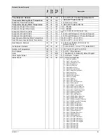
Network Control Property
Variable Name
Page
SNVT Reference
SNVT
Index
Description
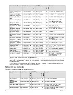
Condenser Refrigerant
Pressure
nvoCondRefPres
47 SNVT_press
30 0 to 410 PSI (0 to 2827 kPA)
Condenser Saturated
Refrigerant Temperature
nvoCondSatRefTmp 47 SNVT_temp_p
105 -15.16 to 185°F (-26.2 to 85°C)
Condenser Water Flow
Rate
nvoCondFlowRate
47 SNVT_flow
15 0 to 1337.01 CFM (0 to 631 L/s)
Condenser Pump Status
nvoCndWPump
48 SNVT_switch
95 0= Pump Commanded Off,
1= Pump Commanded On
*Evaporator Entering
Water Temperature
nvoEntChWTemp
SNVT_temp_p
105 -40 to 257°F (-40 to 125°C)
Evaporator Flow Switch
Status
nvoChillerStat
50 chlr_status
127 0=No Flow, 1=Flow
nvoChillerstat.chw_flow
*Evaporator Leaving
Water Temperature
nvoLvgChWTemp
SNVT_temp_p
105 -40 to 257°F (-40 to 125°C)
Evaporator Pump Run
Hours
nvoEvapPumpHrs
52 SNVT_count_f
51 0
–999,999
Evaporator Water Flow
Rate
nvoEvapFlowRate
53 SNVT_flow
15 0 to 1337.01 CFM (0 to 631 L/s)
Evaporator Pump Status
nvoChWPump
52 SNVT_switch
95 0= Pump Off Request, 1= Pump
On Request
Heat Recovery Entering
Water Temperature
nvoEntHRWTemp
53 SNVT_temp_p
105 -40 to 257°F (-40 to 125°C)
Heat Recovery Leaving
Water Temperature
nvoLvgHRWTemp
54 SNVT_temp_p
105 -40 to 257°F (-40 to 125°C)
Outdoor Air Temperature nvoOutdoorTemp
59 SNVT_temp_p
105 -40°F to 212°F (-40°C to 100°C)
Run Enabled
nvoChillerstat
60 SNVT_chlr_stat
127 0=Off, 1=Run Allowed
Current Alarm
nvoAlarmDescr
67 SNVT_str_asc
36 31 Character Alarm Descriptor
Object Status
nvoStatus
57 SNVT_obj_status 93
*Chiller Enable Output
nvoChillerEnable
31 SNVT_switch
95 0=Disable,
1=Enable
File directory Address
nvoFileDirectory
SNVT_address
114 Address for the file directory
containing descriptors for
configuration files.
*Boldface denotes data/ points for typical minimum integration.
1
The first register in this comma separated list is for compressor 1, the second is for compressor 2, the third is for compressor 3
and the fourth is for compressor 4. You must look at nviCompSelect to determine which compressor’s register is displayed in
this network variable.
2
The first register in this comma separated list is for pump 1, the second is for pump 2. You must look at nviPumpSelect to
determine which pump’s register is displayed in this network variable.
Network Input Variables
Table 6. L
ON
W
ORKS
Network Input Variables
Network Control
Property
Variable Name
Page
SNVT Reference
SNVT
Index
Description
*Capacity Limit
Setpoint
nviCapacityLim
SNVT_lev_percent
81 0 to 100%; Default=100%
*Chiller Enable
Setpoint
nviChillerEnable 32 SNVT_switch
95 0=Disable, 1=Enable
Chiller Mode Setpoint nviMode
36 SNVT_hvac_mode 108 1=HVAC_HEAT, 3=HVAC_COOL,
11=HVAC_ICE; Default=Cool
Compressor Select
nviCompSelect
43 SNVT_count 8
1=Comp 1/Circuit 1, 2=Comp 2/Circuit 2,
3=Comp 3, 4=Comp4

