background image

Si002155E

Partition Plate / Sound Insulations

Removal Procedure

19

5. Partition Plate / Sound Insulations

Warning

Be sure to wait for 10 minutes or more after turning off all power supplies before 
disassembling work.

Step

Procedure

Points

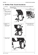
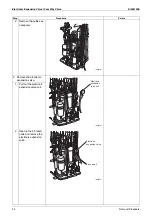
1. Remove the partition 

plate.

When reassembling, fit the 
hook into the bottom frame.

1

2

Detach the snap band 
of compressor harness.

Remove the 3 screws, 
and then the partition 
plate.

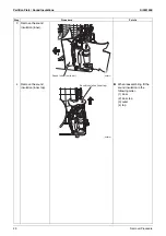
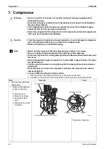
2. Remove the sound 

insulations.

Since the piping ports are 
torn easily, remove the 
sound insulation carefully.

1

Remove the sound 
insulation (top).

2

Remove the sound 
insulation (outer).

(R26211)

Snap band

Partition plate

(R26212)

Hook

Bottom frame

(R26213)

Sound insulation (top)

Sound insulation (outer)

(R26214)

Summary of Contents for 18000 Btu

Page 1: ...REMOVAL PROCEDURE S E R V I C E M A N U A L 18000 24000 Btu h Class Outdoor Unit Inverter Pair Type Si002155E ...

Page 2: ...Service Manual Removal Procedure Outdoor Unit Heat Pump RXM18VVJU RXM24VVJU ...

Page 3: ... 2 2 Outdoor Fan Fan Motor 5 3 Right Side Panel Electrical Box 7 4 PCBs Thermistor ASSY 13 5 Partition Plate Sound Insulations 19 6 Electronic Expansion Valve Four Way Valve 21 7 Compressor 24 Note The illustrations may be slightly different depending on the model ...

Page 4: ...embling work Step Procedure Points 1 Remove the 6 screws and then the top panel 2 Loosen the 2 screws of the protection net 3 Remove the 8 screws of the front panel The front panel can be removed without removing the protection net Loosen the 2 screws that fix the protection net to the front panel Top panel R24835 Protection net R24836 Front panel R21948 ...

Page 5: ...fixing frame to the left and unfasten the 2 hooks 5 6 Unfasten the 2 hooks on the right side Remove the front panel 7 Remove the 4 screws of the discharge grille Step Procedure Points Hook Fan motor fixing frame R21949 Hook Front panel R24837 Discharge grille R21951 ...

Page 6: ...Outer Panels Si002155E 4 Removal Procedure 8 Unfasten the 2 hooks and remove the discharge grille Step Procedure Points R21952 ...

Page 7: ...edure Points 1 Remove the drip proof cover 2 3 Disconnect the connector S70 Release the fan motor lead wire from the 2 hooks S70 fan motor 4 Remove the nut and then the outdoor fan Nut size M8 When reassembling align the mark of the fan rotor with the D cut section of the motor shaft Drip proof cover R24838 Fan motor lead wire Hook S70 R26183 Nut Outdoor fan D cut R24841 13 mm 0 51 inch R18965 ...

Page 8: ...xing frame 6 7 Cut the clamp Unfasten the 3 hooks on the fan motor fixing frame and release the fan motor lead wire When reassembling put the fan motor lead wire through the back of the fan motor to avoid entanglement with the outdoor fan 8 Remove the 4 screws and then the fan motor Step Procedure Points Fan motor fixing frame R24842 Hook R20916 Fan motor fixing frame Slit R21959 Hook Fan motor le...

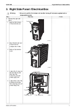
Page 9: ...ight side panel 1 Remove the 2 screws of the terminal cover 2 3 Open the terminal cover and pull down to unfasten the 2 hooks Remove the terminal cover 4 5 Loosen the 7 screws on the terminal strip and disconnect the connecting wire and power supply wire Loosen the 2 nuts of the conduits and remove the connecting wire and power supply wire Terminal cover R24844 R26184 Hook Terminal strip Nut Condu...

Page 10: ... stop valve cover Slide the stop valve cover downward and remove it When reassembling make sure that the 3 hooks are securely fastened 9 10 Pull out the outdoor temperature thermistor holder Remove the outdoor temperature thermistor harness from the slit Step Procedure Points Conduit mounting plate R24847 Stop valve cover R24848 Hook Hook R26185 Slit Thermistor harness Outdoor temperature thermist...

Page 11: ... hooks and remove the right side panel When reassembling make sure to fit the rear hook 2 Remove the electrical box S70 fan motor 1 2 Disconnect the connector S70 Release the fan motor lead wire from the 2 hooks Step Procedure Points Right side panel R26186 Hook Hook Hook R24851 Hook R21317 Hook S70 Fan motor lead wire R26187 ...

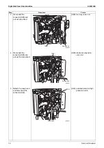
Page 12: ...ap band S80 four way valve coil 4 Disconnect the connector S20 and pull out the snap band S20 electronic expansion valve coil 5 Detach the snap band and disconnect the connector S40 S40 overload protector high pressure switch Step Procedure Points Snap band S80 R26188 R26189 S20 Snap band R26190 S40 Snap band ...

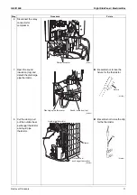
Page 13: ... careful not to lose the fixture for the thermistor 8 Cut the clamp pull out the outdoor heat exchanger thermistor and liquid pipe thermistor Be careful not to lose the clip for the thermistor Step Procedure Points R26191 Relay connector R26192 Sound insulation top Discharge pipe thermistor Fixture R21395 Clamp Outdoor heat exchanger thermistor Liquid pipe thermistor R26193 R20852 Clip ...

Page 14: ...ght Side Panel Electrical Box Si002155E 12 Removal Procedure 9 10 Remove the screw on the partition plate Lift up and remove the electrical box Step Procedure Points Electrical box Partition plate R26194 ...

Page 15: ...emoving the electrical box When reassembling make sure that the 2 hooks are securely fastened 1 2 Remove the screw Unfasten the 2 hooks and remove the switch cover 3 Unfasten the 4 hooks and remove the service monitor PCB cover When reassembling make sure that the 4 hooks are securely fastened 4 Disconnect the 2 connectors S501 and S502 from the service monitor PCB S501 S502 main PCB Switch cover ...

Page 16: ...rth ground screw 2 3 Pull out the snap band Remove the 2 screws of the terminal mounting plate When finished the withstand voltage test make sure that the harness is inside the right side panel Step Procedure Points Projection Service monitor PCB Projection R26198 R26199 Earth ground screw Front view Right view Snap band Withstand voltage harness R26200 ...

Page 17: ...es from the hole 6 Disconnect the 3 terminals for connection and the 4 terminals for power supply Before pulling out the terminals confirm the terminal locations Step Procedure Points R26201 Hook Terminal mounting plate R26202 Hole Harness Terminal for connection Terminal for power supply R26203 Black Terminal for connection White Red R24870 Black Blue Brown White Terminal for power supply R24871 ...

Page 18: ...s of power supply 8 9 Detach the 3 snap bands to release the harness for relay connector Detach the snap band to release the relay harness for compressor 10 Disconnect the connectors S90 and S S90 thermistors S power supply Step Procedure Points R26204 Snap band R26205 Snap band Snap band R26206 S S90 ...

Page 19: ...CBs Thermistor ASSY Removal Procedure 17 11 Remove the 8 screws of the main PCB 12 Lift up the top of the PCB to unfasten the 4 hooks 13 Remove the main PCB Step Procedure Points R26207 Hook R26208 Main PCB R26209 ...

Page 20: ...tor ASSY Si002155E 18 Removal Procedure 3 Remove the thermistor ASSY 1 2 Pull out the 2 snap bands and cut the clamp Remove the thermistor ASSY Step Procedure Points R26210 Clamp Snap band Thermistor ASSY Snap band ...

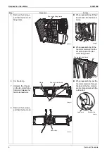
Page 21: ...tion plate When reassembling fit the hook into the bottom frame 1 2 Detach the snap band of compressor harness Remove the 3 screws and then the partition plate 2 Remove the sound insulations Since the piping ports are torn easily remove the sound insulation carefully 1 Remove the sound insulation top 2 Remove the sound insulation outer R26211 Snap band Partition plate R26212 Hook Bottom frame R262...

Page 22: ...re 3 Remove the sound insulation inner 4 Remove the sound insulation inner top When reassembling fit the sound insulation in the following order 1 inner 2 inner top 3 outer 4 top Step Procedure Points Sound insulation inner R26215 Sound insulation inner top R26216 ...

Page 23: ...rom drying Ensure that the temperature is below 120 C 248 F Note Before working make sure that the refrigerant gas is empty in the circuit Be sure to apply nitrogen replacement when heating up the brazed part Do not use a metal saw for cutting pipes by all means because the sawdust comes into the circuit When withdrawing the pipes be careful not to pinch them firmly with pliers The pipes may get d...

Page 24: ...tties as necessary 2 Remove the electronic expansion valve 1 Pull out the electronic expansion valve coil 2 Heat up the 2 brazed parts and remove the electronic expansion valve Step Procedure Points R26218 Electronic expansion valve coil R26219 Electronic expansion valve Brazed part R26220 ...

Page 25: ...Removal Procedure 23 3 Remove the four way valve 1 Remove the screw and then the four way valve coil 2 Heat up the 4 brazed parts and remove the four way valve Step Procedure Points Four way valve coil R26221 Four way valve Brazed part Brazed part R26222 ...

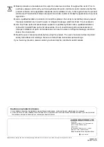
Page 26: ...is empty in the circuit Be sure to apply nitrogen replacement when heating up the brazed part Do not use a metal saw for cutting pipes by all means because the sawdust comes into the circuit When withdrawing the pipes be careful not to pinch them firmly with pliers The pipes may get deformed Provide a protective sheet or a steel plate so that the brazing flame cannot influence peripheries Be caref...

Page 27: ...ompressor make sure to replace the radiation sheet on the back of the overload protector 4 5 6 7 Heat up the brazed part of the discharge side pipe and disconnect it Heat up the brazed part of the suction side pipe and disconnect it Remove the 3 nuts of the compressor Lift up the compressor and remove it Step Procedure Points R26218 Hook A R26223 R26053 Radiation sheet Compressor Brazed part of th...

Page 28: ...Revision History Month Year Version Revised contents 04 2021 Si002155E First edition ...

Page 29: ...essories supplied or specified by Daikin Ask a qualified installer or contractor to install those parts and accessories Use of unauthorized parts and accessories or improper installation of parts and accessories can result in water or refrigerant leakage electrical shock fire or explosion Read the user s manual carefully before using this product The user s manual provides important safety instruc...

Reviews: