Si12-994
Removal of Electrical Box (Pattern 2)
Removal Procedure
7
3. Removal of Electrical Box (Pattern 2)
Procedure
Warning
Be sure to wait for 10 minutes or more after turning off all power
supplies before disassembling work.
Step
Procedure
Points
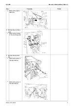
1. Disconnect the
connecting wires.
The US model has a
protection plate on the right
side panel.
Remove the 2 screws to
remove the protection plate.
1
Remove the terminal
board fixing screw.
The wires are fixed to the
terminal board with screws.
2
Remove all the screws
of the connecting wires
and the power supply
wires.
3
Remove the screw of
the earth / ground wire.
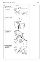
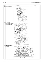
2. Remove the harnesses.
[S20]: White
[S21]: Red
Bundle the harnesses of the
electronic expansion valve
coil with clamp.
Pull out the clamp.
When reassembling, insert
the clamp into one of the
holes.
1
Disconnect the 2
connectors for the
electronic expansion
valve coil [S20] [S21].
Liquid (room A)
Liquid (room B)
Gas (room A)
Gas (room B)
(R17343)
Electronic expansion
valve coil
Conduit
Lock nut
Conduit
mounting plate
Screw
(R17395)
Protection plate
RoomA
RoomB
Terminal board fixing screw
Power supply
Earth /
ground wire
(R18597)
[S20]
[S21]
(R17400)
For the electronic
expansion valve coil
(R17396)

