background image

Inspection and maintenance

Installation and maintenance instructions

37

Daikin Altherma EHS(X/H)(B)-D
Heat pump (indoor unit) with integrated heat accumulator
008.1444099_01 – 11/2018 – EN

WARNING

Temperatures of up to 90 °C can occur during operation
under the protective cover of the indoor unit. During opera-
tion, hot water temperatures of > 60 °C occur.

▪ Touching components during or after operation leads to

a risk of burns.

▪ Water discharged during maintenance and repair work

can cause scalding on contact with the skin.

▪ Before carrying out maintenance and inspection work,

allow the indoor unit to cool down sufficiently.

▪ Wear protective gloves.

WARNING

Touching live parts can result in an electric shock and lead
to potentially fatal injuries and burns.

▪ Before beginning work on live parts, disconnect all cir-

cuits of the system from the power supply (switch off ex-
ternal main switch, disconnect fuse) and secure against
unintentional restart.

▪ The electrical connection and work on the electrical

components should only be performed by electrical en-
gineers in compliance with valid standards and
guidelines as well as the specifications of the energy
supply company.

▪ Device covers and service panels must be replaced as

soon as the work is complete

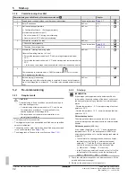
1

Removing the cover and thermal insulation (see 

Chap. 4.4.2

).

2

Check the function of the indoor unit and all installed accessory
components (backup heater, solar system) by checking the tem-
perature display and switching states in the individual operating
modes.

3

If a solar system of the DrainBack type is connected and in oper-
ation, shut it off and empty the collectors.

4

If the indoor unit is operated in a bivalent, alternative system,
switch off all heat generators and deactivate the bi-valence con-
troller.

5

Visual check of the general condition of the indoor unit.

6

Visual check of the water storage tank level (filling level indic-
ator).

▪ If necessary, replenish water (

Chap. 7.2.1

), determine and rem-

edy the reason for the low water level.

7

Check the connection of the safety overflow, drain hose and lid
drain for leaks, free drainage and gradient.

▪ If necessary, clean the safety overflow and drain hose and relay

it; replace damaged parts.

INFORMATION

Thanks to its design, the indoor unit requires very little
maintenance. No corrosion protection equipment is re-
quired (such as expendable anodes). This means there is
no need for maintenance work such as changing the pro-
tective anodes or cleaning the inside of the storage tank.

8

Check the connection of the safety overflow and drain hose for
leaks, free drainage and gradient.

▪ If necessary, clean the safety overflow and drain hose and relay

it; replace damaged parts.

9

Check all electrical components, connections and cables.

▪ Repair damaged parts or replace them.

INFORMATION

If the connection cable of the optional backup heater is
damaged, the entire backup heater must be replaced.

The connection cable cannot be exchanged separately.

10

Check the water pressure of the cold water supply (<6 bar)

▪ and, if necessary, the fitting or adjustment of the pressure redu-

cer.

11

Check the system water pressure on the RoCon+ HP controller
of the indoor unit.

▪ If necessary, top up the water in the heating system until the

pressure display is in the permissible range (see 

Chap. 7.2.2

).

12

Check and clean the filter/sludge separator.

13

Check the minimum flow (see 

Chap. 5.1.4

).

14

Clean the plastic surface of the indoor unit with soft cloths and
mild detergent. Do not use any cleaners with aggressive
solvents (damage to the plastic surface may occur).

15

Re-install the cover (see 

Chap. 4.4.2

).

16

Perform maintenance on the outdoor unit and other heating
components connected to the indoor unit according to the re-
spective installation and operating instructions.

17

Complete the record of maintenance in the operating manual of
the indoor unit provided.

7.2

Inspection and maintenance tasks

Cleaning the protective cover and storage tank

▪ The low-maintenance plastic only needs to be cleaned with soft

cloths and mild detergent.

▪ Do not use any cleaners with aggressive solvents (damage to the

plastic surface may occur).

7.2.1

Filling, topping up the storage tank

CAUTION

Filling the storage tank with too high a water pressure or
too high a flow speed can cause damage to the indoor unit.

▪ Only fill with a water pressure <6 bar and a flow speed

<15 l/min.

Summary of Contents for Altherma 3 ECH2O

Page 1: ...ions Heat pump indoor unit with integrated heat accumulator English Installation and maintenance instructions Daikin Altherma 3 ECH2O EHSX B 04P30D EHSX B 04P50D EHSH B 04P30D EHSX B 08P30D EHSX B 08P50D EHSH B 08P30D EHSH B 08P50D 11 2018 ...

Page 2: ......

Page 3: ...on on the electrical connection 23 4 7 5 Connecting the heat pump outdoor unit 23 4 7 6 Connecting the outside temperature sensor optional 24 4 7 7 External switching contact 24 4 7 8 EBA external requirement request 24 4 7 9 Connecting an external heat generator 24 4 7 10 Connecting the room thermostat 25 4 7 11 Connection of optional RoCon system components 26 4 7 12 Connecting the HP convector ...

Page 4: ...Cleaning and user mainten ance must not be carried out by children without supervision Make up the power supply in accord ance with IEC 60335 1 via a separ ator device which exhibits contact separation in all poles with a contact opening distance that provide full disconnection in accordance with overvoltage category III All the electrical work must only be carried out by electrically qualified ex...

Page 5: ...valent solar system connec tion Biv Only applies to indoor units with cooling function Handling instructions 1 Handling instructions are shown as a list Actions for which the sequential order must be maintained are numbered è Results of actions are identified with an arrow 1 2 Safety instructions for installation and operation 1 2 1 General WARNING Devices that have not been set up and installed c...

Page 6: ...ible The electronic control system must not be exposed to whether effects like rain and snow under any circum stances The storage tank may not be exposed to continuous dir ect sunlight as the UV radiation and the effects of the weather will damage the plastic The indoor unit must be installed protected from frost Make sure that the supply company does not provide corrosive domestic water Suitable ...

Page 7: ... con veying water for human consumption TRWI and in addition the country specific legislation When operating the indoor unit with additional heat source the stor age tank temperature may exceed 65 C above all when solar en ergy is used For this reason some form of scalding protection needs to be in cluded when you install the system hot water mixing device e g VTA32 If the indoor unit is connected...

Page 8: ...n structions and operating manual to the operator and advise him that these documents must be made available at all times and be stored in the immediate vicinity of the device Document the handover by filling out the installation and instruc tion forms together with the owner and sign them 2 2 Warranty conditions The legal guarantee conditions fundamentally apply Our more ex tensive warranty condi...

Page 9: ... pump indoor unit with integrated heat accumulator 008 1444099_01 11 2018 EN 3 Product description 3 1 Design and components Outside of the device Fig 3 1 Design and components Outside of the device 1 Upper side of the device Fig 3 2 Design and components Top of the device 1 1 For legend see Tab 3 1 ...

Page 10: ...mp indoor unit with integrated heat accumulator 008 1444099_01 11 2018 EN Internal structure 04P30D 08P30D Fig 3 3 Design and components Internal struc ture 04P30D 08P30D Biv 1 Internal structure 04P50D 08P50D Fig 3 4 Design and components Internal struc ture 04P50D 08P50D Biv 1 1 For legend see Tab 3 1 ...

Page 11: ...hanger stain less steel for domestic hot water heating 38 Connection for dia phragm expansion vessel 13 Heat exchanger stain less steel for storage tank charging or heating support 39 Control system housing 14 Biv heat exchanger stainless steel for char ging with external heat generator e g pressur ised solar system 3UVB 1 3 way switch valve in ternal heat generator cir cuit 15 Connection for opti...

Page 12: ...cational training for the respective activity and who have taken part in advanced training sessions recognised by the relevant responsible authority These include in par ticular certified heating engineers qualified electricians and HVAC specialists who because of their professional training and expert knowledge have experience in the professional installation and maintenance of heating cooling an...

Page 13: ...nd forklift trucks are suitable for transporting it Scope of delivery Indoor unit pre mounted Bag of accessories see Fig 4 5 Document pack Fig 4 5 Contents of bag of accessories Item Designation Item Designation A Handles only required for transport G O ring B cover panel H Cable tie C Hose connecting piece for safety overflow I Plug bracket D Assembly wrench J Venting hose E Ball valve K Drain ho...

Page 14: ...ion lines Recommended minimum distances To the wall back 100 mm sides 500 mm To the ceiling 1200 mm at least 480 mm Distances from the outdoor unit When selecting the installation location the information in the table Tab 4 3must be taken into account Maximum refrigerant line length between the indoor and outdoor unit 30 m Minimum refrigerant line length between the indoor and outdoor unit 3 m Max...

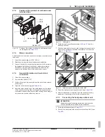
Page 15: ...teral holding burls upwards with your fingers 2 stem from above with the thumbs 3 Remove the front screen to the front 3 Fig 4 7 Remove the front screen 4 After completing the installation Place the front screen straight directly above the rotary switch of the RoCon HP Press on the top and bottom until the front screen is securely en gaged again 4 4 2 Remove the protective cover 1 Undo the screws ...

Page 16: ...ler housing 3 Hook in the cover on the controller housing with the lateral hooks Fig 4 13 Hooking in the cover 4 4 5 Removing the bottom thermal insulation CAUTION The thermal insulation Fig 4 9 item A consists of pres sure sensitive EPP moulded parts that can be easily dam aged if not handled correctly Only remove the thermal insulation in the order stated below and in the stated directions Do no...

Page 17: ...eir mountings to ensure a very strong or continuous escape of liquid can occur Before putting on a plug bracket make sure that the stir rup engages in the coupling groove To do so insert the coupling far enough into the mounting that the groove is visible through the plug bracket mounting Insert the plug bracket up to the end stop The connections of the heating inflow and return flow can be direc ...

Page 18: ... a suitable tool Fig 4 20 Cut out in thermal insulation 4 4 8 Making the hood opening 1 With the heating inflow and return flow directed upwards Cut the hood along the perforation with a suitable tool Fig 4 21 Making the hood opening 4 4 9 Installing the rotary switch of the controller 1 Place the rotary switch on the rotary switch holder of the RoCon HP and press it on Fig 4 22 Putting on the rot...

Page 19: ...r not part of the DB connection kit but in cluded with EKSRPS4 C Flow rate limiter FlowGuard D Solar inflow connection on the storage tank Tab 4 5 4 5 4 Installation of the P connection kit The optional P connection kit for Biv device types allows better ac cess for connecting the inflow and return flow lines of a pressurised solar system or another external heat generator on the storage tank The ...

Page 20: ...tall a scalding protection hot water mixer device e g VTA32 INFORMATION The indoor unit is equipped with a pressure sensor The system pressure in monitored electronically and can be displayed with the device switched on Nevertheless we recommend installing a mechanical pres sure gauge between the indoor unit and the diaphragm ex pansion vessel for example Install the pressure gauge so that it is e...

Page 21: ...upply switch off ex ternal main switch disconnect fuse and secure against unintentional restart Establishment of the electrical connection and work on electrical components should only be performed by elec trical technicians in compliance with valid standards and guidelines as well as the specifications of the en ergy supply company and the instructions in this manual Never make constructional cha...

Page 22: ... H B D Heat pump indoor unit with integrated heat accumulator 008 1444099_01 11 2018 EN 4 7 1 Overall connection diagram Fig 4 31 Overall connection diagram for the electrical connection during the device installation for the legend and pin assignment of the printed circuit board see Chap 10 6 ...

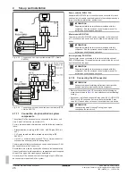
Page 23: ...to Off 3 Switch off the circuit breaker in the junction box of the domestic power supply 4 Open the controller housing see Chap 4 4 4 5 Insert the cable through one of the cable glands into the interior of the controller housing When cutting and laying cables to be connected make sure that the controller housing can be brought into the service position without any tension Fig 4 33 Cable gland 6 Ma...

Page 24: ...contact Fig 4 36 enables the op erating mode of the indoor unit to be switched over The current operating mode is switched by a changing resistance value Tab 4 7 The changeover of the operating mode is only ef fective for a long as the external switching contact is closed The operating mode has an effect on the direct circuit of the indoor unit as well as all other heating circuits connected to th...

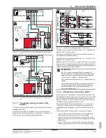
Page 25: ... water preparation and the backup heating setting of the Config of external heat source parameter DHW heating support Main menu Settings Ext source or Connection to K1 and K3 if two external heat generators are used setting of the Config of external heat source parameter Two external heat generators Main menu Settings Ext source In this case K1 connects the external heat generator e g gas fired or...

Page 26: ...to enable remote adjustment of operating modes and target room temperatures from another room INFORMATION Separate installation instructions are included with this component See the enclosed control system manual for instructions on setting and operation Mixer module EHS157068 The mixer module EHS157068 can be connected to the indoor unit J13 circuit board connector and is controlled by the electr...

Page 27: ... or G plus condensing boiler is connected the AUX switching function parameter and AUX delay time parameter must be set according to the desired function Main menu Settings Inputs Outputs See Controller operating instructions chapter Parameter settings Precise information on the electrical connection and the re quired parameter settings for such bivalent heating sys tems are available on the Inter...

Page 28: ...Inputs Outputs is activated see controller operating instruc tions the heat pump is switched to normal or a mode with higher temperatures depending on the utility company signal For this purpose the SG1 SG2 floating switching contacts of the in telligent controller must be connected to the J8 connector Smart Grid and EVU connections on the RoCon BM2C printed circuit board see Fig 4 45 As soon as t...

Page 29: ...solute Time Minimum 1 h 4 Check whether additional refrigerant is needed for primer filling fill if necessary 5 Open the stop valves on the exterior unit completely until the stop Slightly tighten 6 Reinstall the valve caps 7 Check that the storage tank temperature sensors are inserted to a depth of tDHW1 80 cm and tDHW2 60 cm 4 9 Filling the system Only fill the indoor unit after all installation...

Page 30: ...frigerant The heating and hot water system has been filled and pressurised to the correct pressure see Chap 7 2 2 The storage tank is filled up to the overflow see Chap 7 2 1 Optional accessories have been installed and connected up The heating system s control valves are open 5 1 2 Starting the unit and start up INFORMATION Please observe the operating instructions of the RoCon HP controller INFO...

Page 31: ...in menu Information Values The flow rate must be at least 480 l h see Controller operating instructions INFORMATION The indoor unit controller constantly monitors the flow rate of the internal heat generator circuit Different minimum flow rate values are required depending on the active oper ating mode Heating operating mode 480 l h Cooling operating mode 660 l h Automatic thawing function Defrost...

Page 32: ... temperatures below 0 C only if a wa ter temperature of at least 5 C is guaranteed in the heating system and the storage tank We recommend not to operate the installation in ex tremely frosty conditions The indoor unit is fully connected The refrigerant system is dehumidified and filled with the specified amount of refrigerant The heating and hot water system has been filled and pressurised to the...

Page 33: ...the heating system check the installation pressure and adjust if necessary max 3 bar see Chap 7 2 2 5 Carry out a visual inspection for leaks on all connection points internally Seal any leaks that occur in a professional manner 6 Set the controller to the required operating mode 7 If a solar system is connected commission it according to the enclosed instructions After shutting off the solar syst...

Page 34: ...ver a substitute for careful system planning Please visit our website for more diagrams Item Meaning 1 Cold water distribution network 2 Hot water distribution network 3 Heating inflow 4 Heating return flow 5 Mixer circuit 6 Circulation optional 7 Check valve return valve 7a Non return valves 8 Solar circuit 9 Gas line 10 Liquid line 3UV DHW 3 way distribution valve hot water heater 3UVB1 3 way mi...

Page 35: ... unit with integrated heat accumulator 008 1444099_01 11 2018 EN Item Meaning tK Solaris trap temperature sensor tR Solaris return flow temperature sensor TS Solaris storage cylinder temp sensor V Fan vaporiser VS Scalding protection VTA32 Tab 6 1 Fig 6 1 Hydraulic diagram Biv types with pressurised solar system ...

Page 36: ...on This documentation must be kept for at least 5 years INFORMATION Persons who hold a certificate of qualification for work on stationary refrigeration systems heat pumps and air con ditioning systems for the European area in accordance with the F Gas Certification Regulation EU 2015 2067 are certified Up to 3 kg or 5 t CO2 equivalent Total refrigerant charge Category II certificate of competence...

Page 37: ...r leaks free drainage and gradient If necessary clean the safety overflow and drain hose and relay it replace damaged parts INFORMATION Thanks to its design the indoor unit requires very little maintenance No corrosion protection equipment is re quired such as expendable anodes This means there is no need for maintenance work such as changing the pro tective anodes or cleaning the inside of the st...

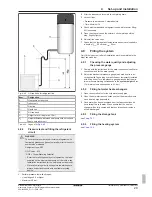
Page 38: ...r heating switch the parameter off again Main menu User 1x load Without installed solar system 1 Connect the filling hose with non return valve 1 2 to the Solar inflow connection Fig 7 1 item 1 2 Fill the storage tank of the indoor unit until water escapes at the overflow connection Fig 7 1 item 23 3 Remove the filling hose with non return valve 1 2 With installed solar system 1 Install the fillin...

Page 39: ... item 4 The combined filling and draining valve must remain open in order to read off the water pressure on the external pressure gauge 8 Switch on the power supply of the indoor unit 9 In the controller RoCon HP in the Operating mode menu se lect the Heating operating mode Main menu Operating mode After the start phase the indoor unit runs in hot water heat ing operation 10 Constantly check the w...

Page 40: ...the operating mode 1 Select the Operating mode menu Main menu Oper ating mode 2 Select the correct operating mode The controller does not respond to inputs The controller s operating system has crashed RESET the controller To do this disconnect the system from the power supply for at least 10 s and then switch on again Operating data are not updated The controller s operating system has crashed RE...

Page 41: ...arameters Main menu Settings Ext source Water volume in heating system too low Check the admission pressure in the expansion tank and wa ter pressure if necessary top up the heating water and adjust the admission pressure see Chap 7 2 2 Domestic hot water preparation is taking too much of the output of the heat pump Check the settings of the Config of external heat source parameter Main menu Setti...

Page 42: ...ow temperature Check mains supply of the backup heater EKBUxx Thermal contactor STB on the backup heater EKBUxx has triggered Unlock System is in Heating operating mode Switch the operating mode to Cooling Outside temperature 4 C The heat pump has automatically switched to Heating oper ating mode to be able to guarantee frost protection if the out side temperature continues to fall No room cooling...

Page 43: ...pecified maximum pressure If necessary drain sufficient water until the pressure is in the middle of the permissible range Safety pressure relief valve is stuck Check the safety pressure relief valve and if necessary re place it Turn the red knob on the safety pressure relief valve anti clockwise If you can hear a rattling noise the safety pres sure relief valve needs replacing Tab 8 1 Possible ma...

Page 44: ...ermissible min imum value Insufficient water in the heating system Check the heating system for leaks top up wa ter Pressure sensor DS defective Check replace E8006 Pressure sensor DS Pressure drop in heating system too high Pressure drop too fast Check the heating system for leaks Pressure sensor DS defective Check replace E8007 Pressure sensor DS Water pressure in heating system too high Water p...

Page 45: ...emperature sensor tV BH Inflow temperature tV BH 75 C Feed temperature of backup heater tV BH is too high Inflow temperature sensor providing incorrect val ues Temperature sensor or connecting cable de fective Check replace Contact problem A1P jumper on X3A E9006 Inflow temperature sensor tV BH Inflow temperature tV BH 65 C E9007 Circuit board A1P IG circuit board defective Communication between t...

Page 46: ...overload protection has triggered Pressure difference in the refrigerant cir cuit between high and low pressure side too high 26 bar Refrigerant compressor defective Inverter circuit board in the heat pump outdoor unit defective Refrigerant compressor inverter circuit board wir ing poor contact Filled refrigerant quantity too high Check replace Service valves in the heat pump outdoor unit not open...

Page 47: ... error Sensor or connecting cable defective Check replace E9023 Storage tank temperature sensor tDHW1 or tDHW2 Hot water sensor error E9024 Pressure sensor S1NPH in the heat pump outdoor unit Pressure sensor E9025 Outlet temperature sensor R2T in the heat pump out door unit Return flow temperature sensor error E9026 Intake temperature sensor R3T in the heat pump out door unit Intake pipe sensor er...

Page 48: ...r defective Inverter circuit board in the heat pump outdoor unit defective Wiring poor contact Service valves in the heat pump outdoor unit not open Check eliminate cause replace If necessary contact a service technician E9032 Electrical components Refrigerant compressor defective Inverter circuit board in the heat pump outdoor unit defective Check replace If necessary contact a service technician...

Page 49: ...nverter circuit board in the heat pump outdoor unit defective Check replace If necessary contact a service technician E9041 Transmission fault Electrical components Communication between the heat pump outdoor unit and heat pump indoor unit lost Wiring or connections poor contact No heat pump outdoor unit connected Printed circuit board A1P defective Main circuit board in the heat pump outdoor unit...

Page 50: ... fluid return flow Check the refrigerant filling capacity and check for leaks Check the power transistor Check the outer inverter conductor plate Check that the current flow LED flashes at regular intervals Check that the correct replacement part has been installed Check that the outer main conductor plate is re ceiving a power supply Check that the power supply meets the regula tions Check for fr...

Page 51: ...sor s connection and wiring Check the operation of the expansion valve fluid return flow Check the refrigerant filling capacity and check for leaks Check the outer inverter conductor plate Check that the current flow LED flashes at regular intervals Check that the correct replacement part has been installed Check that the outer main conductor plate is re ceiving a power supply E9052 Software Compr...

Page 52: ... W8007 Water pressure in heating system too high Warning message Water pressure has exceeded permissible maximum value Diaphragm expansion vessel defective or incor rect admission pressure set Check replace Max Pressure parameter setting too low Set the parameter if necessary If the setting is correct drain water to reduce system pressure Tab 8 2 Fault codes INFORMATION Observe maximum temperature...

Page 53: ... Emergency operation If the heat pump fails the backup heater or another external heat generator can be used as an emergency heater If Emergency oper ation is set to Yes emergency operation is automatically activated in the event of an error Otherwise emergency operation can only be started in the event of an error via the error screen see enclosed controller operating instructions ...

Page 54: ...es no frost protection for the connec ted heat distribution system 9 1 1 Draining the storage tank 1 Switch off the main switch and secure against restarting 2 Connect the drain hose to the combined filling and draining filling connection combined filling and draining BA ac cessories Fig 9 1 item A and to a waste water drainage point which is at least at ground level INFORMATION If no combined fil...

Page 55: ... drain the water content of the storage tank 9 1 2 Draining the heating circuit and hot water circuit 1 Connect the drain hose to the KFE cock of the indoor unit 2 Open the KFE cock on the indoor unit 3 Drain the heating and hot water circuits 4 Disconnect the heating flow and return and the cold water feed and hot water discharge from the indoor unit 5 Connect the discharge hose on the heating in...

Page 56: ...dly design of the in door unit we have established requirements to ensure environ mentally friendly disposal Proper disposal in compliance with the respective national regulations of the country of use is the respons ibility of the user owner The designation of the product means that electrical and electronic products may not be disposed of together with unsorted domestic waste Proper disposal in ...

Page 57: ...er Heat insulation EPP Storage tank Total storage capacity litres 294 477 Maximum permissible storage water temperature C 85 Heat consumption at stand by and at 60 C kWh 24 h 1 5 1 7 Drinking water heat exchanger stainless steel 1 4404 Water capacity heat exchanger litres 27 1 28 2 28 1 Domestic water heat exchanger surface m2 5 60 5 80 5 90 Max operating pressure bar 6 0 Storage tank charging hea...

Page 58: ...4 Backup heater optional 3 Total filled weight 15 Backup heater protec tion class optional 4 Max permissible operat ing pressure PMS heat ing 16 Backup heater fuse op tional 5 Total storage capacity 17 Output backup heater power supply optional To select 0 kW no ex ternal heat source 6 Max permissible operat ing temperature Tmax 18 Refrigerant circuit Item Designation Item Designation 7 Standby he...

Page 59: ...perature sensor Fig 10 2 Characteristic of temperature sensor tDHW1 tV BH Item Designation RS Sensor resistance NTC t Temperature tDHW1 Storage tank temperature sensor Tab 10 18 Legend for Fig 10 2 Fig 10 3 Characteristic of temperature sensor tR tV tDHW2 tDC Item Designation RS Sensor resistance NTC t Temperature tR Return flow temperature sensor Tab 10 19 Legend for Fig 10 3 Fig 10 4 Characteris...

Page 60: ...mmax Tab 10 23 from the Aroom for the available size of the install ation room 4 For calculated dm take the minimum area of the ventilation opening VAmin for natural ventilation between the installation room and the adjacent room Tab 10 25 5 The device can be installed if 2 ventilation openings are provided between the installation room and adjacent room 1 each at top and bottom Bottom opening The...

Page 61: ... 34 186 0 30 168 0 26 149 dm kg Minimum area of the ventilation opening VAmin cm2 0 23 131 0 19 112 0 16 93 0 13 75 0 09 56 0 06 38 0 03 19 Tab 10 25 Minimum area of the ventilation opening Example Total refrigerant charge 1 84 kg installation room 15 m 1 From Tab 10 23 mc 1 84 kg è Amin 29 m è Minimum room size requirement NOT fulfilled ventilation opening required 2 Check with Tab 10 24 Aroom in...

Page 62: ...allation and maintenance instructions 62 Daikin Altherma EHS X H B D Heat pump indoor unit with integrated heat accumulator 008 1444099_01 11 2018 EN 10 6 Electrical connection diagram Fig 10 6 Electrical connection diagram ...

Page 63: ... Plug connection for internal wiring bridging plug J5 Pressure sensor plug connection AUX Switching contact outputs A A1 A2 B B1 J6 Plug connection mains voltage EKBUxx Backup heater J8 Plug connection for EXT DS Pressure sensor Plug connection for EBA EBA Switching contact for external requirement request Plug connection for Smart Grid EVU switching contacts EXT Switching contact for external ope...

Page 64: ...11 Notes Installation and maintenance instructions 64 Daikin Altherma EHS X H B D Heat pump indoor unit with integrated heat accumulator 008 1444099_01 11 2018 EN 11 Notes ...

Page 65: ...11 Notes Installation and maintenance instructions 65 Daikin Altherma EHS X H B D Heat pump indoor unit with integrated heat accumulator 008 1444099_01 11 2018 EN ...

Page 66: ...11 Notes Installation and maintenance instructions 66 Daikin Altherma EHS X H B D Heat pump indoor unit with integrated heat accumulator 008 1444099_01 11 2018 EN ...

Page 67: ...ign and components 9 Dirt filter 19 Disposal 56 E Electrical installation 21 Emergency operation 53 F Filling connection 54 Filling Heating system 29 Filling Storage tank 29 H Heating system Emptying 54 Hydraulic connection Example connections 34 I Installation area 14 Installation site 13 Intended use 6 L Legal requirements 36 M Maintenance 36 Malfunctions 43 Minimum distance 14 P Protective cove...

Page 68: ...008 1444099_01 11 2018 EN Copyright Daikin ...

Reviews: