5 Electrical installation
Installation manual
22
EGSAH/X06+10DA9W(G)
Daikin Altherma 3 GEO
4P569811-1 – 2019.02
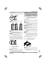
NOTICE
To prevent communication problems due to cable
breakdown, do NOT exceed the minimum bend radius of
the Ethernet cable.
5.14.4
Electricity meter
If the LAN adapter is connected to an electricity meter, make sure it
is an
electrical pulse meter
.
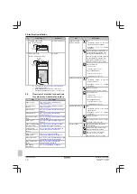
Requirements:
Item
Specification
Type
Pulse meter
(5 V DC pulse
detection)
Possible number of pulses
▪ 100 pulse/kWh
▪ 1000 pulse/kWh
Pulse duration
Minimum On
time
10 ms
Minimum OFF
time
100 ms
Measurement type
Depends on the installation:
▪ Single‑phase AC meter
▪ Three‑phase
AC
meter
(balanced loads)
▪ Three‑phase
AC
meter
(unbalanced loads)
INFORMATION
It is required that the electricity meter has a pulse output
that can measure the total energy injected INTO the grid.
Suggested electricity meters
Phase
ABB reference
Single
2CMA100152R1000 B21 212-100
Three
2CMA100166R1000 B23 212-100
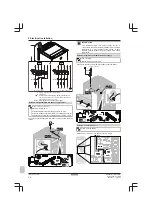
To connect the electricity meter
NOTICE
To prevent damage to the PCB, it is NOT allowed to
connect the electrical wiring with the connectors already
connected to the PCB. First connect the wiring to the
connectors, then connect the connectors to the PCB.
1
Open the following (see
"3.2.1 To open the indoor unit" on
):
1
Top panel
3
1
2
4
2
User interface panel
3
Front panel
4
Main switch box cover
2
Connect the electricity meter to LAN adapter terminals
X2A/1+2.
1×
2×
S1S
1
2
2
1
INFORMATION
Mind the polarity of the cable. The positive wire MUST be
connected to X2A/1; the negative wire to X2A/2.
WARNING
Make sure to connect the electricity meter in the correct
direction, so that it measures the total energy injected
INTO the grid.
5.14.5
Solar inverter/energy management
system
INFORMATION
Before installation, confirm that the solar inverter/energy
management system is equipped with the digital outputs
required to connect it to the LAN adapter. For more
information, see the installer reference guide.
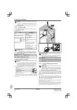
Connector X1A is for the connection of the LAN adapter to the digital
outputs of a solar inverter/energy management system, and allows
for the integration of the Daikin Altherma system in a Smart Grid
application.
X1A/N+L supply a 230 V AC detection voltage to the input contact of
X1A. The 230 V AC detection voltage enables the detection of the
state (open or close) of the digital inputs and does NOT supply
power to the rest of the LAN adapter PCB.
Make sure X1A/N+L are protected by a fast acting circuit breaker
(rated current 100 mA~6 A, type B).
The rest of the wiring to X1A differs depending on the digital outputs
available on the solar inverter/energy management system and/or on
the Smart Grid operation modes that you want the system to run in.
Summary of Contents for Altherma 3 GEO
Page 38: ......
Page 39: ......
Page 40: ...4P569811 1 2019 02 Copyright 2019 Daikin 4P569811 1 0000000S ...


