background image

5 Electrical installation

Installation manual

12

ETVH/9W(G)

Daikin Altherma 3 H HT F

4P586454-1 – 2019.07

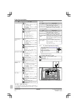
Backup

heater type

Backup

heater

capacity

Power

supply

Maximum

running

current

Z

max

*6V

2 kW

1N~ 230 V

(a)

9 A

4 kW

1N~ 230 V

(a)

17 A

(b)(c)

0.22 Ω

6 kW

1N~ 230 V

(a)

26 A

(b)(c)

0.22 Ω

2 kW

3~ 230 V

(d)

5 A

4 kW

3~ 230 V

(d)

10 A

6 kW

3~ 230 V

(d)

15 A

*9W

3 kW

3N~ 400 V

4 A

6 kW

3N~ 400 V

9 A

9 kW

3N~ 400 V

13 A

(a)

6V

(b)

Electrical equipment complying with EN/IEC 61000-3-12
(European/International Technical Standard setting the
limits for harmonic currents produced by equipment
connected to public low-voltage systems with input
current >16 A and ≤75 A per phase).

(c)

This equipment complies with EN/IEC 61000‑3‑11
(European/International Technical Standard setting the
limits for voltage changes, voltage fluctuations and
flicker in public low-voltage supply systems for
equipment with rated current ≤75 A) provided that the
system impedance Z

sys

 is less than or equal to Z

max

 at

the interface point between the user's supply and the
public system. It is the responsibility of the installer or
user of the equipment to ensure, by consultation with the
distribution network operator if necessary, that the
equipment is connected only to a supply with a system
impedance Z

sys

 less than or equal to Z

max

.

(d)

6T1

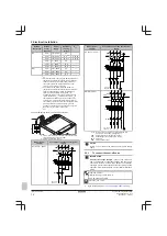
Connect the backup heater power supply as follows:

X6M

F1B

Q1DI

a

b

a

Factory-mounted cable connected to the backup heater
contactor inside the switch box (K5M)

b

Field wiring (see table below)

Model (power

supply)

Connections to backup heater power

supply

*6V (6V: 1N~ 230 V)

1N~, 50 Hz
230 V AC

SWB

4

3

6

5

2

1

K5M

14

13

Q1DI

1

2

3

4

5

6

7

8

F1B

I

I

I

I

N

L

X6M

BRN

GRY

BLU1

BLU2

Model (power

supply)

Connections to backup heater power

supply

*6V (6T1: 3~ 230 V)

SWB

3~, 50 Hz
230 V AC

4

3

6

5

2

1

K5M

14

13

1

2

3

4

5

6

7

8

F1B

I

I

I

I

Q1DI

L1

L2

L3

X6M

BRN

GRY

BLU1

BLU2

*9W (3N~ 400 V)

3N~, 50 Hz
400 V AC

SWB

Q1DI

L1

L2

L3

N

1

2

3

4

5

6

7

8

F1B

I

I

I

I

X6M

2

1

K5M

4

3

6

5

14

13

BRN

GRY

BLK

BLU

F1B

Overcurrent fuse (field supply). Recommended fuse:
4‑pole; 20 A; curve 400 V; tripping class C.

K5M

Safety contactor (in the lower switch box)

Q1DI

Earth leakage circuit breaker (field supply)

SWB

Switch box

X6M

Terminal (field supply)

NOTICE

Do  NOT  cut  or  remove  the  backup  heater  power  supply
cable.

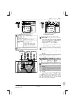
5.2.3

To connect the shut-off valve

INFORMATION

Shut-off valve usage example.

 In case of one LWT zone,

and  a  combination  of  underfloor  heating  and  heat  pump
convectors,  install  a  shut-off  valve  before  the  underfloor
heating to prevent condensation on the floor during cooling
operation. For more information, see the installer reference
guide.

Wires: 2×0.75 mm²

Maximum running current: 100 mA

230 V AC supplied by PCB

[2.D] 

Shut off valve

1

Open the following (see 

"3.2.1 To open the indoor unit" 

[

4

 4]):

Summary of Contents for Altherma 3 H HT F Series

Page 1: ...manual Daikin Altherma 3 H HT F English Installation manual Daikin Altherma 3 H HT F ETVH16S18DA6V G ETVH16S23DA6V G ETVH16S18DA9W G ETVH16S23DA9W G ETVX16S18DA6V G ETVX16S23DA6V G ETVX16S18DA9W G ETV...

Page 2: ...ou vyu v ny v souladu s na imi pokyny odpov daj n sleduj c m norm m nebo normativn m dokument m u skladu sa slijede im standardom ima ili drugim normativnim dokumentom ima uz uvjet da se oni koriste u...

Page 3: ...up heater 19 6 2 5 Configuration wizard Main zone 20 6 2 6 Configuration wizard Additional zone 20 6 2 7 Configuration wizard Tank 21 6 3 Weather dependent curve 21 6 3 1 What is a weather dependent c...

Page 4: ...liance or an operating electric heater 3 1 1 Installation site requirements of the indoor unit The indoor unit is designed for indoor installation only and for the following ambient temperatures Space...

Page 5: ...wing cases 3 2 2 To lower the switch box on the indoor unit 45 3 3 2 To connect the drain hose to the drain 46 When you need access to the high voltage switch box 2 T25 5 If you need access to the hig...

Page 6: ...in hose to the drain See 3 3 2 To connect the drain hose to the drain 46 3 Slide the indoor unit into position 4 Adjust the height of the leveling feet to compensate for floor irregularities The maxim...

Page 7: ...the water piping 4 2 1 To connect the water piping 1 Connect the O rings and shut off valves to the outdoor unit water connection pipes of the indoor unit 2 Connect the outdoor unit field piping to t...

Page 8: ...ms galvanic corrosion cells that cause severe damage to the system Therefore it is important that the water treatment is correctly executed by a qualified water specialist a glycol with corrosion inhi...

Page 9: ...taps after all air is purged 4 Check for water leaks 4 2 6 To insulate the water piping The piping in the complete water circuit MUST be insulated to prevent condensation during cooling operation and...

Page 10: ...0 75 1 25 mm Must be sheathed Maximum length 200 m See below LAN adapter System requirements LAN adapter System requirements The requirements posed on the Daikin Altherma system depend on the LAN ada...

Page 11: ...1Y to X11YB The necessity of separate normal kWh rate power supply to indoor unit b X2M 5 6 depends on the type of preferential kWh rate power supply Separate connection to the indoor unit is required...

Page 12: ...ual to Zmax d 6T1 Connect the backup heater power supply as follows X6M F1B Q1DI a b a Factory mounted cable connected to the backup heater contactor inside the switch box K5M b Field wiring see table...

Page 13: ...with transistor output check the polarity The positive polarity MUST be connected to X5M 6 and X5M 4 the negative polarity to X5M 5 and X5M 3 1 Open the following see 3 2 1 To open the indoor unit 44...

Page 14: ...rm output 3 Wire between X2M and A4P A4P Installation of EKRP1HB is required A Y1 7 B A B 7 9 X2M A4P Y1 YC X1M a b a Installation of EKRP1HB is required b Prewiring between X2M 7 9 and Q1L thermal pr...

Page 15: ...1 2 3 2 User interface panel 3 Upper switch box cover 2 Connect the changeover to external heat source cable to the appropriate terminals as shown in the illustration below A X1 X2 L N B A B A4P X2M...

Page 16: ...3 Fix the cable with cable ties to the cable tie mountings NOTICE Make sure to select and install the safety thermostat according to the applicable legislation In any case to prevent unnecessary trip...

Page 17: ...u can access the installer settings using two different methods However NOT all settings are accessible via both methods If so the corresponding table columns in this chapter are set to N A not applic...

Page 18: ...t cannot be adjusted Backup heater type The backup heater is adapted to be connected to most common European electricity grids The type of backup heater must be set on the user interface For units wit...

Page 19: ...E 0D Glycol Filled system Is the system filled with glycol 0 No 1 Yes 6 2 4 Configuration wizard Backup heater The backup heater is adapted to be connected to most common European electricity grids I...

Page 20: ...ontrol Defines how the operation of the unit is controlled There are 3 possibilities Control In this control Leaving water Unit operation is decided based on the leaving water temperature regardless t...

Page 21: ...op can be programmed This feature puts a stop to tank heating even if the setpoint has NOT been reached Only program a storage stop when tank heating is absolutely undesirable Code Description 5 2 6 0...

Page 22: ...eaving water for different ambient temperatures For example if leaving water temperature is in general fine but at low ambient temperatures too cold raise the slope so that leaving water temperature i...

Page 23: ...mum and minimum setpoints You cannot configure the curve with temperatures that are higher or lower than the set maximum and minimum setpoints for that zone or for the tank When the maximum or minimum...

Page 24: ...in external room thermostat control For more info about the functionality see 6 4 1 Main zone 423 Code Description 3 A C 06 External room thermostat type for the additional zone 1 1 contact 2 2 contac...

Page 25: ...9 B Sensors External sensor Ext amb sensor offset Averaging time 9 C Bivalent Bivalent Boiler efficiency Temperature Hysteresis 9 9 Power consumption control Power consumption control Type Limit Limi...

Page 26: ...islation Between the local supply panel and the outdoor unit Between indoor unit and outdoor unit Between the local supply panel and the indoor unit Between the indoor unit and the valves if applicabl...

Page 27: ...e list Example Pump 4 Select OK to confirm Result The actuator test run starts It stops automatically when done 30 min To stop the test run manually 1 In the menu go to Stop test run 2 Select OK to co...

Page 28: ...ask him her to keep it for future reference Inform the user that he can find the complete documentation at the URL mentioned earlier in this manual Explain the user how to properly operate the system...

Page 29: ...ter cold water IN loose nut 3 4 b2 Domestic hot water hot water OUT loose nut 3 4 c1 Water IN connection c2 Water OUT connection d Pump e Backup heater f Shut off valve male female 1 g Expansion vesse...

Page 30: ...wireless On OFF thermostat wireless Ext thermistor External thermistor Heat pump convector Heat pump convector Position in switch box English Translation Position in switch box Position in switch box...

Page 31: ...ed Normally closed Normally open Normally open Safety thermostat contact 16 V DC detection voltage supplied by PCB Safety thermostat contact 16 V DC detection voltage supplied by PCB English Translati...

Page 32: ...e 2 core 2 core 3 core R2T External sensor floor or ambient Only for KRTETS signal 2 core 3m included A13P P1 P2 LAN adapter A14P P1 P2 user interface Only for Human Comfort Interface Only for KRTR wi...

Page 33: ......

Page 34: ......

Page 35: ......

Page 36: ...4P586454 1 2019 07 Copyright 2019 Daikin 4P586454 1 0000000U...

Reviews: