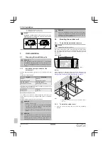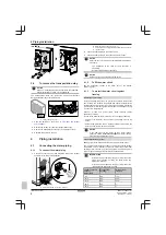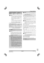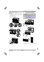
5 Electrical installation
Installation manual
11
EPRA14~W1
Daikin Altherma 3 H HT
4P586100-1 – 2019.07
The Hydronic Piping Calculation tool also calculates the maximum
hydronic piping length from the indoor unit to the outdoor unit based
on the emitter pressure drop or the other way around.
The Hydronic Piping Calculation tool is part of the Heating Solutions
Navigator
which
can
be
reached
via
professional.standbyme.daikin.eu
Please contact your dealer if you have no access to Heating
Solutions Navigator.
This recommendation ensures good operation of the unit, however,
local regulations may differ and shall be followed.
5
Electrical installation
DANGER: RISK OF ELECTROCUTION
WARNING
Rotating fan.
Before powering ON or servicing the outdoor
unit, make sure that the discharge grille covers the fan as
protection against a rotating fan. See:
▪
"6.2 To install the discharge grille" on page 14
▪
"6.3 To remove the discharge grille, and put the grille in
safety position" on page 15
WARNING
ALWAYS use multicore cable for power supply cables.
CAUTION
Do NOT push or place redundant cable length in the unit.
NOTICE
The distance between the high voltage and low voltage
cables should be at least 50 mm.
5.1
About electrical compliance
Only for EPRA14~18DAV3
Equipment complying with EN/IEC 61000‑3‑12 (European/
International Technical Standard setting the limits for harmonic
currents produced by equipment connected to public low-voltage
systems with input current >16 A and ≤75 A per phase.).
5.2
Guidelines when connecting the
electrical wiring
Tightening torques
Item
Tightening torque (N•m)
M4 (X1M, X2M)
1.2~1.5
M4 (earth)
5.3
To connect the electrical wiring on
the outdoor unit
1
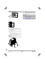
Open the switch box cover. See
.
2
Insert the cables at the back of the unit, and route them through
the factory-mounted cable sleeves into the switch box. For the
power supply, use the factory-mounted cable.
d
c2
b2
c1
b1
a1
a2
a1+a2
Power supply cable (factory-mounted cable)
b1+b2
Interconnection cable (field supply)
c1+c2
(optional) Drain tube heater cable (field supply)
d
Cable sleeves (factory-mounted)
3
Inside the switch box, connect the wires to the appropriate
terminals, and fix the cables with cable ties. See:
▪
"5.3.1 In case of V3 models" on page 11
▪
"5.3.2 In case of W1 models" on page 12
5.3.1
In case of V3 models
1
Power supply cable
:
▪ Use the factory-mounted cable, which is already routed
through the frame.
▪ Connect the wires to the terminal block.
▪ Fix the cable with a cable tie.
Use the factory-mounted cable.
Wires: 1N+GND
Maximum running current: Refer to name plate on unit.
—
L N PE
b
a
L
N


