background image

3 Unit installation

Installation manual

6

EPRA14~W1

Daikin Altherma 3 H HT

4P586100-1 – 2019.07

g

Discharge grille (upper + lower part)

h

Installation manual – Discharge grille

NOTICE

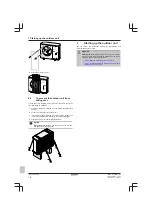
Unpacking  –  Front  corners.

  When  you  remove  the  front

packaging  corners,  hold  the  box  containing  the  discharge
grille to prevent it from falling.

3

Unit installation

3.1

Preparing the installation site

WARNING

The  appliance  shall  be  stored  in  a  room  without
continuously  operating  ignition  sources  (example:  open
flames, an operating gas appliance or an operating electric
heater).

3.1.1

Installation site requirements of the
outdoor unit

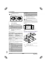
Mind  the  spacing  guidelines.  See  figure  1  on  the  inside  of  the  front
cover.

Translation of text on figure 1:

English

Translation

General

General

No top-side obstacle

No top-side obstacle

Top-side obstacle

Top-side obstacle

Wall height unrestricted

Wall height unrestricted

The outdoor unit is designed for outdoor installation only, and for the
following ambient temperatures:

Cooling mode

10~43°C

Heating mode

–28~35°C

Special requirements for R32

The  outdoor  unit  contains  an  internal  refrigerant  circuit  (R32),  but
you  do  NOT  have  to  do  any  refrigerant  field  piping,  or  refrigerant
charging.

Mind the following requirements and precautions:

WARNING

▪ Do NOT pierce or burn.

▪ Do  NOT  use  means  to  accelerate  the  defrosting

process  or  to  clean  the  equipment,  other  than  those
recommended by the manufacturer.

▪ Be  aware  that  R32  refrigerant  does  NOT  contain  an

odour.

WARNING

The appliance shall be stored so as to prevent mechanical
damage and in a well-ventilated room without continuously
operating  ignition  sources  (example:  open  flames,  an
operating gas appliance or an operating electric heater).

WARNING

Make  sure  installation,  servicing,  maintenance  and  repair
comply  with  instructions  from  Daikin  and  with  applicable
legislation  (for  example  national  gas  regulation)  and  are
executed only by authorised persons.

3.2

Mounting the outdoor unit

3.2.1

To provide the installation structure

NOTICE

Level.

 Make sure the unit is level.

Use 4 sets of M12 anchor bolts, nuts and washers. Provide at least
150  mm  of  free  space  below  the  unit.  Additionally,  make  sure  the
unit  is  positioned  at  least  100  mm  above  the  maximum  expected
level of snow.

Anchor points

800

(mm)

479

Pedestal

When  installing  on  a  pedestal,  make  sure  that  the  discharge  grille
still  can  be  put  in  its  safety  position.  See 

"6.3  To  remove  the

discharge grille, and put the grille in safety position" on page 15

.

800

479 

a

≥150

(mm)

4× M12

a

Make sure not to cover the drain hole in the bottom plate of
the unit.

3.2.2

To install the outdoor unit

1

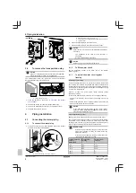
Carry  the  unit  by  its  slings,  and  put  it  onto  the  installation
structure.

Summary of Contents for Altherma 3 H HT

Page 1: ...Installation manual Daikin Altherma 3 H HT English Installation manual Daikin Altherma 3 H HT EPRA14DAV3 EPRA16DAV3 EPRA18DAV3 EPRA14DAW1 EPRA16DAW1 EPRA18DAW1 ...

Page 2: ...all height unrestricted 1000 X X H 150 H 500 500 300 500 500 300 300 1000 500 1000 500 500 1000 500 1000 500 1000 300 X X H X X H General mm 3D124412 300 150 100 Top side obstacle No top side obstacle 1 ...

Page 3: ...m в соответствии с положениями 10 11 12 13 14 15 16 17 18 under iagttagelse af bestemmelserne i enligt villkoren i gitt i henhold til bestemmelsene i noudattaen määräyksiä za dodržení ustanovení předpisu prema odredbama követi a z zgodnie z postanowieniami Dyrektyw în urma prevederilor 19 20 21 22 23 24 25 ob upoštevanju določb vastavalt nõuetele следвайки клаузите на laikantis nuostatų pateikiamų...

Page 4: ...uurin sallittu lämpötila TS TSmin Alhaisin matalapainepuolen lämpötila L C TSmax Suurinta sallittua painetta PS vastaava kyllästyslämpötila M C Kylmäaine N Varmuuspainelaitteen asetus P bar Valmistusnumero ja valmistusvuosi katso mallin nimikilpi Maximální přípustný tlak PS K bar Minimální maximální přípustná teplota TS TSmin Minimální teplota na nízkotlaké straně L C TSmax Saturovaná teplota odpo...

Page 5: ... 1 1 About this document Target audience Authorised installers Documentation set This document is part of a documentation set The complete set consists of General safety precautions Safety instructions that you must read before installing Format Paper in the box of the indoor unit Operation manual Quick guide for basic usage Format Paper in the box of the indoor unit User reference guide Detailed ...

Page 6: ...s and precautions WARNING Do NOT pierce or burn Do NOT use means to accelerate the defrosting process or to clean the equipment other than those recommended by the manufacturer Be aware that R32 refrigerant does NOT contain an odour WARNING The appliance shall be stored so as to prevent mechanical damage and in a well ventilated room without continuously operating ignition sources example open fla...

Page 7: ...Insulate the drain hose Install a drain tube heater field supply To connect the drain tube heater see 5 3 To connect the electrical wiring on the outdoor unit on page 11 NOTICE Provide at least 150 mm of free space below the unit Additionally make sure the unit is positioned at least 100 mm above the expected level of snow Use the drain plug with O ring and a hose for drainage 1 2 a b c c 3 d a Dr...

Page 8: ... or the installer reference guide 4 1 3 To protect the water circuit against freezing About freeze protection Frost can damage the system To prevent the hydraulic components from freezing the software is equipped with special frost protection functions such as water pipe freeze prevention and drain prevention see the installer reference guide that include the activation of pump in case of low temp...

Page 9: ...he oxidation of glycols no automotive glycol is used because their corrosion inhibitors have a limited lifetime and contain silicates which can foul or plug the system galvanized pipes are NOT used in glycol systems since the presence may lead to the precipitation of certain components in the glycol s corrosion inhibitor Adding glycol to the water circuit reduces the maximum allowed water volume o...

Page 10: ...the liquid inside the piping from freezing Protection against freezing the glycol will prevent the liquid inside the piping from freezing NOTICE The required concentration might differ depending on the type of glycol ALWAYS compare the requirements from the table above with the specifications provided by the glycol manufacturer If necessary meet the requirements set by the glycol manufacturer The ...

Page 11: ... mm 5 1 About electrical compliance Only for EPRA14 18DAV3 Equipment complying with EN IEC 61000 3 12 European International Technical Standard setting the limits for harmonic currents produced by equipment connected to public low voltage systems with input current 16 A and 75 A per phase 5 2 Guidelines when connecting the electrical wiring Tightening torques Item Tightening torque N m M4 X1M X2M ...

Page 12: ... 5 mm 1 2 3 1 2 3 3 Optional Drain tube heater cable Make sure the heating element of the drain tube heater is completely inside the drain tube Route the cable through the frame Connect the wires to the terminal block and the earth screw Fix the cable with cable ties Wires 2 GND 0 75 mm Wiring must be double insulated Maximum power allowed for drain tube heater 115 W 0 5 A L N PE 1 2 4 Optional Po...

Page 13: ...se field supply Recommended fuse 4 pole 16 A or 20 A fuse C curve Q1DI Earth leakage circuit breaker 30 mA field supply 2 Interconnection cable indoor outdoor Route the cable through the frame Connect the wires to the terminal block make sure the numbers match with the numbers on the indoor unit and the earth screw Fix the cable with a cable tie Wires 3 GND 1 5 mm 1 2 3 1 2 3 3 Optional Drain tube...

Page 14: ...peratures Required accessory delivered with the unit Thermistor fixture 1 2 3 Click 4 5 6 7 6 Finishing the outdoor unit installation 6 1 To close the outdoor unit NOTICE When closing the outdoor unit cover make sure that the tightening torque does NOT exceed 4 1 N m 1 1 2 3 2 4 4 3 3 3 1 6 2 To install the discharge grille Install the lower part of the discharge grille 1 Insert the hooks 2 Insert...

Page 15: ...ball studs 8 7 9 Fix the 6 remaining screws 9 6 6 3 To remove the discharge grille and put the grille in safety position WARNING Rotating fan Before powering ON or servicing the outdoor unit make sure that the discharge grille covers the fan as protection against a rotating fan See 6 2 To install the discharge grille on page 14 6 3 To remove the discharge grille and put the grille in safety positi...

Page 16: ...he cables and the outdoor unit to prevent the cables from scratching the paint field supply 4 Attach the ends of the cables and tighten them NOTICE Discharge grille Do NOT use too much force to prevent damage to the discharge grille 7 Starting up the outdoor unit See the indoor unit installation manual for configuration and commissioning of the system WARNING Rotating fan Before powering ON or ser...

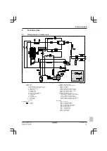
Page 17: ... k Air heat exchanger l PCB cooling m Accumulator n Muffler Refrigerant flow Heating Cooling E1HC Crankcase heater E1HHEX Plate heat exchanger heater M1C Compressor M1F Fan motor PRV Refrigerant pressure relief valve S1PH High pressure switch 5 6 MPa S2PH High pressure switch 4 17 MPa S1PL Low pressure switch S1NPH High pressure sensor Y1E Electronic expansion valve main Y3E Electronic expansion v...

Page 18: ...ted circuit board ACS A5P Printed circuit board flash BS1 BS4 A1P Push button switch C1 C4 A1P A2P Capacitor DS1 A1P DIP switch E1H Drain tube heater field supply E1HC Crankcase heater E1HHEX E3HHEX Plate heat exchanger heaters F1U Field fuse field supply F1U F4U A2P Fuse F6U A1P Fuse T 5 0 A 250 V H1P H7P A1P Light emitting diode service monitor is orange HAP A1P Light emitting diode service moni...

Page 19: ...X K2R A1P Magnetic relay Y2S K2R A4P Magnetic relay E1H K3R A1P Magnetic relay Y3S K4R A1P Magnetic relay E1HC K2M K11M A2P Magnetic contactor L1R L4R Reactor M1C Compressor motor M1F Fan motor PS A2P Switching power supply Q1DI Earth leakage circuit breaker 30 mA field supply R1 R2 A2P Resistor R1T Thermistor outdoor air R2T Thermistor compressor discharge R3T Thermistor compressor suction R4T Th...

Page 20: ...4P586100 1 2019 07 Copyright 2019 Daikin 4P586100 1 0000000I ...

Reviews: