EKHWS150~3 E300B3Z2
Domestic hot water tank for air to water heat pump system
4PW54951-1
Installation manual
3
Safety devices
■
Thermal protector — The booster heater in the domestic hot
water tank is equipped with a thermal protector. The thermal
protector is activated when the temperature becomes too high.
When activated, the protector has to be reset on the domestic
hot water tank by pressing the red button (for access, remove
the electrical box lid).
■
Pressure relief valve — A pressure relief valve (field supply) in
accordance with relevant local and national regulations, and with
an opening pressure of maximum 10 bar must be connected to
the pressure relief valve connection.
■
If a discharge pipe is connected to the pressure relief device it
must be installed in a continuously downward direction and in a
frost-free environment. It must be left open to the atmosphere.
■
The supplied temperature and pressure relief valve and T-piece
must be correctly installed to the hot water outlet.
Outlook diagram
Outlook diagram, see
Installation guidelines
■
Keep in mind the following guidelines when installing the
domestic hot water tank:
■
The installation location is frost-free.
■
Make sure to make the piping in size 1" or more (and reduce to
3/4" at the inlet of the tank) as to have sufficient water volume in
the piping between indoor unit and domestic hot water tank.
■
Locate the domestic hot water tank in a suitable position to
facilitate ease of maintenance; remember access is required to
the electrical box. Refer to the grey-coloured zones indicated in
.
■
Provide a connection for the pressure relief valve blow-off and
drain.
■
To avoid back siphonage it is advised to install a non-return
valve on the water inlet of the domestic hot water tank in
accordance with local and national regulations.
■
Take care that in the event of a leak, water can not cause any
damage to the installation space and surroundings.
■
The domestic hot water tank model
EKHWS(U)150B3V3 can be floor or wall
mounted. In case of wall mounting, wall
mounting kit EKWBSWW150 is required
(separate ordering).
Installing the domestic hot water tank
1
Check if all domestic hot water tank accessories (see
2
When floor mounting, place the domestic hot water tank on a
level surface. When wall mounting (only for EKHWS(U)150B3V3
model), make sure the wall is sturdy. In both cases, make sure
the domestic hot water tank is mounted level.
3
Apply thermal paste to the thermistor and insert the thermistor
as deep as possible in the thermistor socket. Fix using the nut
provided.
Connecting the water circuits
Refer to the chapter "Typical application examples" described in the
installation manual delivered with the indoor unit for details on
connecting the water circuits and the motorised 3-way valve.
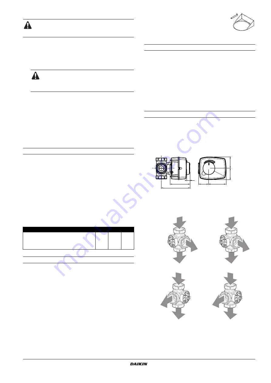
Connecting the 3-way valve
1
Refer to the figure below before making the connection.
2
Installation position.
It is advised to connect the 3-way valve as close as possible to
the indoor unit. It can be installed in accordance with one of the
following four configurations.
■
The domestic hot water tank relief valve connections
may not be used for other purpose.
■
Do not install heaters without thermal cut-outs.
The electrical box lid must only be opened by a
licensed electrician.
Switch off the power supply before opening the
electrical box lid.
1
Hot water and pressure relief valve connection
2
Recirculation hole
3
Flow inlet connection from the main indoor unit
4
Return outlet connection to the main indoor unit
5
Cold water connection
6
Domestic hot water tank electrical box cable entry
7
Thermistor socket
8
Threaded thermistor hole for use with solar kit option. See
Installation manual EKSOLHWAV1.
9
Domestic hot water tank electrical box cable entry for use with
optional solar kit
Domestic hot water tank model
H1
H2
H3
H4
EKHWS150B3V3
900
475
185
605
EKHWS200B3V3/Z2
1150
630
200
830
EKHWS300B3V3/Z2
1600
630
200
830
figure A
figure B
figure C
figure D
1
From
AD
indoor unit
2
To domestic hot water tank
3
To room heating
13
77
111
38
67
44
44
1
2
3
1
3
2
1
2
3
1
3
2
Summary of Contents for Altherma EKHWS150B3V3
Page 10: ...4PW54951 1 Copyright Daikin ...


