Page 18 of 60
IM 817-4
R
S
J
A
B
B
8-1/2"
(216mm)
13-3/4"
(349mm)
J
A
13-3/4"
(349mm)
8-1/2"
(216mm)
Air Flow
Air Flow
R
S
R
S
16-1/8"
(410mm)
11"
(279mm)
Air Flow
R
S
16-1/8"
(410mm)
J
11"
(279mm)
K
H
Air Flow
J
K
H
R
S
J
A
B
B
8-1/2"
(216mm)
13-3/4"
(349mm)
J
A
13-3/4"
(349mm)
8-1/2"
(216mm)
Air Flow
Air Flow
R
S
78 = Opposite End Drain Low Capacity Steam Coil
79 = Opposite End Drain High Capacity Steam Coil
12 = Low Electric Heat Coil
13 = High Electric Heat Coil
Heating Coils
00 = None
Cooling Coils
V = 2-Row CW Coil
S = 3-Row CW Coil
W = 4-Row CW Coil
G = Direct Expansion Coil
Y = 5-Row CW Coil
Heating Only
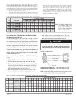
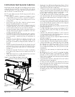
Figure 42 - Hot Water Heating Only Unit
(Coils 65, 66, 67)
Cooling Only
Unit
Series
S07 S10 S13 S15
Suction Line O.D. (in/mm)
3
⁄
4
19
3
⁄
4
19
7
⁄
8
22
7
⁄
8
22
Liquid LIne O.D. (in/mm)
1
⁄
4
6.35
1
⁄
4
6
3
⁄
8
10
3
⁄
8
10
Notes:
1. All coils have same end supply and return connections.
2. Steam coils have a factory installed pressure equalizing valve and
a 24" (610mm) long pressure equalizing line which terminates
in a
1
⁄
2
" M.P.T. fitting.
3. Steam/hot water connections may be same end as cooling
coil connections, but they are recommended to be opposite
end to facilitate piping. (Must be opposite end when using AAF
controls.)
4. Cooling condensate drain pan is shipped sloped down towards
the cooling coil connections but is field reversible.
5. Electric heating coil power connections are right end only.
Junction box has 1"(25mm) and 2" (51mm) (trade size)
knockouts, 10
1
⁄
2
" (267mm) from right end of the unit.
6. For limitations with coil combinations see tables 4, 5, 8 and 9.
7. Coil stubs are
7
⁄
8
" I.D. (female) and terminate 9" (229mm) from the
end of the unit.
8. Steam coils are 1
1
⁄
8
" female (sweat) connections and terminate
9” (229mm) from the end of the unit.
9. DX coils (G) have O.D. sweat connections. Interconnecting tube
by others. See table 7 for correct tubing size.
Table 6 - Dimensions
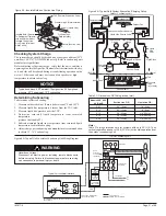
Table 7 - DX Coil (G) Connection Tubing
L.H. Connections
Electric Heating
Only
S
= Supply
R
= Return
R.H. Connections
L.H. Connections
R.H. Connections
R.H. Connections
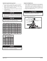
Table 4 - Heating Only – Coil Position/Combinations In Air Stream (one coil per position) Note: X indicates Available.
Face and Bypass
Valve
First Position in Air Stream
Second Position in Air Stream
AVS
AVV
AVV Elect..
65 66 67 68 69 78 79
Z
X
X
12 13
Z
X
Heating Coils
65 = 1-Row Hot Water Coil
66 = 2-Row Hot Water Coil
67 = 3-Row Hot Water Coil
68 = Low Capacity Steam Coil
69 = High Capacity Steam Coil
Cooling Coils
Z = None
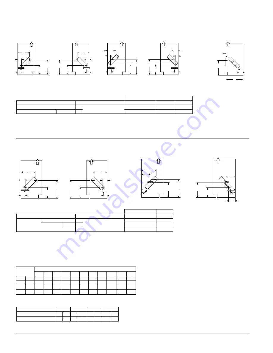
Table 5 - Cooling Only – Coil Position/Combinations In Air Stream (one coil per position) Note: X indicates Available.
Face and Bypass
Valve
First Position in Air Stream
Second Position in Air Stream
AVS
AVV
Y
V
S
W
00
X
X
G
00
X
L.H. Connections
Figure 45 - Chilled Water Only Unit (Coils S, W, V)
Figure 46 - Direct Expansion Cooling Only Unit (Coil G)
R.H. Connections
L.H. Connections
R.H. Connections
Note: For opposite end drain steam coils (code 78,79) Return (R)
is 7
1
⁄
4
"(184mm) from bottom of unit and H - 2"(51mm) from back
of unit.
Figure 43 - Steam Heating Only Unit
(Coils 68, 69, 78, 79)
Figure 44- Electric Heating Only Unit
(Coils 12, 13)
Coil Headers, Locations
S
= Supply
R
= Return
J
Air Flow
14"
(356mm)
L
Junction Box
Unit
Dimensions
Depth
A B C D E F G H I J K
in 16
5
⁄
8
3
3
⁄
4
12
1
⁄
4
4
7
⁄
8
7
3
⁄
4
1
5
⁄
8
10
1
⁄
8
2
3
⁄
4
2
7
⁄
8
5
5
/
8
3
5
mm 422 95 311 124 198 41 257 70
73 143
76 127
in
21
7
⁄
8
9
17
1
⁄
2
10
1
⁄
8
13
6
7
⁄
8
15
3
⁄
8
8
8
1
⁄
8
10
7
⁄
8
8
1
⁄
4
10
1
⁄
4
mm 556 229 445 257 330 175 391 203 206 276 210 260
S
= Supply
R
= Return
LL
SL
J
D
C
7-1/4"
(184mm)
Air Flow
11-3/4"
(299mm)
LL
SL
J
B
Air Flow
13-3/4"
(349mm)
11-3/4"
(299mm)
D


