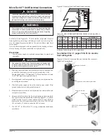
IM 817-4
Page 41 of 60
Setup and Adjustments
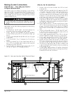
Switching Setpoint Dials
To switch setpoint dials:
1. Remove the sensor from the mounting base.
2. Rotate the smooth setpoint dial so that it points straight up.
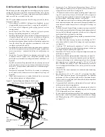
3. As shown in Figure 111, insert the Allen wrench through the hole
in the back of the printed wiring board (A) and push gently until
the smooth setpoint dial is free.
4. Press the serrated setpoint dial into place on the sensor,
making sure that the dial points straight up.
5. Replace the sensor on the mounting base.
Repairs and Replacement
No repair options available. Call your local Daikin
representative for sensor replacement.
Wiring
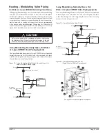
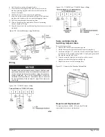
Figure 109 - 111048101 Sensor Wiring
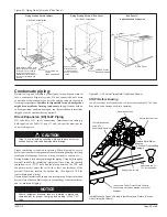
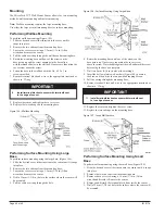
Figure 108 - Surface Mounting Using Small Base
Terminal Block on 111048101 Sensor
Shielded cable should always be used. However, shielded cable
generally is not required, except in electrically noisy environments,
such as near gas ignition systems, radar or magnetic resonance
imaging equipment, etc. It is the responsibility of others to
determine what constitutes an “electrically noisy” environment
for each installation. Refer to table 25, page 38 for maximum
wire length.
6. Pull the cable or wiring through the hole.
7. Place the small base against the wall, (with the arrow on
the base pointing up) and mark the screw holes using the
base as a template.
8. Drill two 8 mm (5/16 in.) holes at the markings.
9. Insert the hollow plastic wall anchors (Figure 108), position
the base, and then drive the two pan-head tapping screws.
10. Pull the wiring through the mounting base.
11. Wire to the appropriate terminals to the small mounting
base as shown in “
Wiring”
.
12. Snap the sensor into the small mounting base (cover screw is not
required).
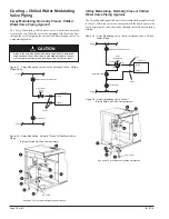
Figure 110 - 111048102 and 111048103 Sensor Wiring
Figure 111 - Removing the Standard Setpoint Dial
A
Setpoint Dial
NOTICE

