Page 6 of 60
IM 817-4
Models
Shipping Weight
Approx. Shipping
Filter Size
Unit Length*
Number
AVS, AVV,
lbs. (kg)
Weight lbs. (kg)
in. (mm)
in. (mm)
of Fans
AVR, AVB
16
5
/
8
"Units 21
7
/
8
"Units
S07
350 (168)
370 (163)
10 x 36.5 x 1
62 (1575)
2
(254 x 927 x 25)
S10
425 (193)
445 (202)
10 x 48.5 x 1
74 (1880)
3
(254 x 1232 x 25)
S13
495 (225)
525 (238)
10 x 60.5 x 1
86 (2174)
4
(254 x 1551 x 25)
S15
570 (259)
600 (272)
Two: 10 x 36.5 x 1
98 (2489)
4
(254 x 927 x 25)
Disconnect all electrical power before servicing unit.
Electrical shock will cause severe injury or death.
Hazardous Voltage!
Use copper conductors only. Unit terminals are not designed to
accept other types of conductors. Failure to do so may cause
damage to the equipment.
Personal injury hazard. Wear protective gloves to avoid possible
cuts and abrasions from exposed edges. Avoid contact with sharp
edges.
Cleaning agents may cause serious damage to internal
components, such as aluminum coils and electronic controls,
etc. Do not operate unit ventilator while building maintenance
cleaning agents are in use.
Pre-Installation Considerations
Properly Identify Unit Ventilator(s)
To be sure the correct unit ventilator(s) is/are installed in the
correct location(s), the installer must check the packing list and unit
identification/tagging number(s) against the plans.
Further, the unit data
plate, (see figure 1) located on the lower right end of the unit ventilator,
contains specific information of standard components as listed in Table 1.
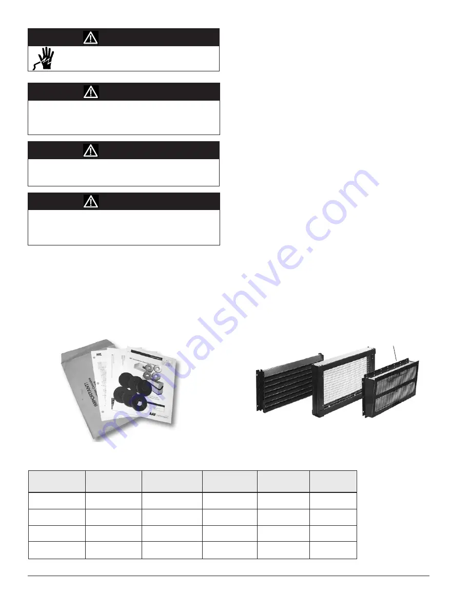
Figure 4 - Shipping Envelope Contents - Located in right end
compartment of unit.
Uncrate and Inspect the Unit Ventilator(s)
Carefully remove the packaging, remaining alert to any signs of shipping
damage. Be careful not to discard components that may be included with
the packaging. (You may want to retain some or all of the packaging
to provide jobsite unit location information and temporary protection
for the unit ventilator after installation.) Be sure to dispose of plastic
packaging and protective cardboard properly, in accordance with local
recycling rules and guidelines.
If unit is damaged, file a claim with the carrier. Notify the local Daikin
Unit Ventilator representative immediately.
Wall Openings, Louvers, and VentiMatic™
Shutter
Prior to unit installation, be sure that the exterior wall openings and
louvers, as applicable, are ready and in accordance with the job plans.
Vertical Floor Models AVS, AVV, AVB, AVR are typically installed
in front of a wall opening containing a properly sized louver that is
designed to let in outside air while preventing water (such as rain) from
getting past the louver and into the unit itself. A weather-tight seal keeps
unwanted air and moisture from entering the occupied space. See Figures
6 through 21, and table 1 for various louver details.
VentiMatic
™
Shutter Assembly
In many installations, a Daikin VentiMatic Shutter Assembly is specified.
See figure 5. This one-way shutter is a continuously variable, gravity
actuated, room exhaust vent that operates in direct response to positive
static pressure. It opposes any airflow into the room and allows a slight
positive pressure.
It is important that the VentiMatic shutter and unit ventilator louvers
are mounted on the same wall. This neutralizes the effect of the wind.
Forcing excess air into the room through the unit ventilator louver
overcomes the same wind pressure that works to keep the VentiMatic
shutter closed. This prevents room air exhausting from the room through
the VentiMatic shutter.
Note: Birdscreen and louver are shipped in one (1) piece.
Figure 5 – VentiMatic Shutter Assembly
Outside
Louver
VentiMatic Shutter
Roomside
Relief Air
Table 2 - Approximate Shipping Weights, Physical Data
* Measurement is without end panels. All unit ventilators are 30" (762 mm) high.
DANGER
WARNING
CAUTION
WARNING


