IM 817-7
2
www.DaikinApplied.com
General Data . . . . . . . . . . . . . . . . . . . . . . . . . . . . . . . . . 3
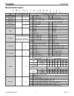
Model Nomenclature . . . . . . . . . . . . . . . . . . . . . . . . . . 3
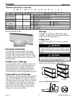
Receiving & Handling . . . . . . . . . . . . . . . . . . . . . . . . . 4
Visible Loss or Damage . . . . . . . . . . . . . . . . . . . . . . . 4
Concealed Loss or Damage . . . . . . . . . . . . . . . . . . . . 4
Storage . . . . . . . . . . . . . . . . . . . . . . . . . . . . . . . . . . . . 4
Lifting Unit . . . . . . . . . . . . . . . . . . . . . . . . . . . . . . . . . . 4
Pre-Installation Information . . . . . . . . . . . . . . . . . . . . . 5
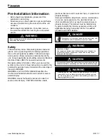
Safety . . . . . . . . . . . . . . . . . . . . . . . . . . . . . . . . . . . . . 5
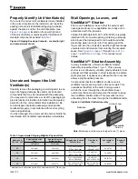
Properly Identify Unit Ventilator(s). . . . . . . . . . . . . . . . 6
Uncrate and Inspect the Unit Ventilator(s) . . . . . . . . . 6
Wall Openings, Louvers, and VentiMatic™ Shutter . . 6
VentiMatic™ Shutter Assembly . . . . . . . . . . . . . . . . . . 6
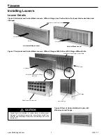
Installing Louvers . . . . . . . . . . . . . . . . . . . . . . . . . . . . . 7
Louver Details . . . . . . . . . . . . . . . . . . . . . . . . . . . . . . . 7
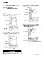
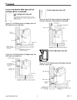
Louver Installation With Typical Unit Configurations
Typical Installation Methods . . . . . . . . . . . . . . . . . . . 10
Installing the VentiMatic Shutter Assembly . . . . . . . 11
Before Setting the Unit in Place . . . . . . . . . . . . . . . . 12
Removing Unit from the Skid . . . . . . . . . . . . . . . . . . 12
Mounting Holes, Piping and Electrical Knockout
Locations & Dimensions . . . . . . . . . . . . . . . . . . . . . . 13
Reversing Drain Pan Slope. . . . . . . . . . . . . . . . . . . . 13
Typical Floor Unit Installation . . . . . . . . . . . . . . . . . . 15
Unit Ventilator Installation . . . . . . . . . . . . . . . . . . . . . 16
Make Piping Connections . . . . . . . . . . . . . . . . . . . . . 16
Water Coil Connections. . . . . . . . . . . . . . . . . . . . . . . 17
Coil Headers, Locations . . . . . . . . . . . . . . . . . . . . . . . 18
Heating Only Units . . . . . . . . . . . . . . . . . . . . . . . . . . 18
Cooling Only Units . . . . . . . . . . . . . . . . . . . . . . . . . . 19
Heat/Cool Units . . . . . . . . . . . . . . . . . . . . . . . . . . . . . 20
Reheat Units . . . . . . . . . . . . . . . . . . . . . . . . . . . . . . . 22
Typical Valve Packages . . . . . . . . . . . . . . . . . . . . . . . 23
2-Way and 3-Way Hot Water and Chilled Water
Modulating Valve Selection . . . . . . . . . . . . . . . . . . . . 29
Typical Piping Arrangements . . . . . . . . . . . . . . . . . . 30
Heating – Hot Water End of Cycle Valve Piping . . . . 30
Cooling – Chilled Water EOC Valve Piping . . . . . . . . 31
Typical Water Coil Piping - EOC Valve Piping. . . . . . 31
Steam – Typical Modulating Valve Piping . . . . . . . . . 32
Typical Steam Coil Piping . . . . . . . . . . . . . . . . . . . . . 33
Heating – Modulating Valve Piping . . . . . . . . . . . . . . 34
Cooling – Chilled Water Modulating
Valve Piping. . . . . . . . . . . . . . . . . . . . . . . . . . . . . . . . 35
Condensate Piping:. . . . . . . . . . . . . . . . . . . . . . . . . . 36
Unit Ventilator Split Systems Guidelines . . . . . . . . . 37
Checking System Charge . . . . . . . . . . . . . . . . . . . . . 38
Determining Subcooling . . . . . . . . . . . . . . . . . . . . . . 38
Determining System Superheat . . . . . . . . . . . . . . . . 39
Superheat Adjustment. . . . . . . . . . . . . . . . . . . . . . . . 40
Making Control Connections . . . . . . . . . . . . . . . . . . . 40
MicroTech Unit Mounted DDC Control Components –
Models AVS, AVV, and AVR. . . . . . . . . . . . . . . . . . . . 40
Typical MicroTech Wiring –
115Volt / 60Hz / 1 Phase. . . . . . . . . . . . . . . . . . . . . . 44
MicroTech Unit Electrical Connections . . . . . . . . . . 46
MicroTech Wall Mounted Sensor. . . . . . . . . . . . . . . . 47
Typical Connections For Temperature Sensor
Applications. . . . . . . . . . . . . . . . . . . . . . . . . . . . . . . . 48
Making Control Connections . . . . . . . . . . . . . . . . . . . 51
Digital Ready™ – Face & Bypass Control
Components Model AVS . . . . . . . . . . . . . . . . . . . . . . 51
Typical Wiring Diagram . . . . . . . . . . . . . . . . . . . . . . . 53
Digital Ready Face and Bypass Control . . . . . . . . . . 53
Digital Ready Unit Mounted Temperature Sensor
. . . . . . . . . . . . . . . . . . . . . . . . . . . . . . 54
Digital Ready – Damper Actuator Specifications
Digital Ready Unit Electrical Connections. . . . . . . . . 56
Controls by Others Components. . . . . . . . . . . . . . . . 57
Typical Controls by Others Wiring Diagram – Units
with Optional EC Motor with Variable Airflow
Typical Controls by Others Wiring Diagram – Units
with Optional EC Motor with Variable Airflow, Valve
Control. . . . . . . . . . . . . . . . . . . . . . . . . . . . . . . . . . . . 60
Controls by Others – Field Installed . . . . . . . . . . . . . 61
Controls by Others – Electrical Connections. . . . . . . 62
Electric Heat Wiring Diagram – Typical. . . . . . . . . . . 64
Electric Heating . . . . . . . . . . . . . . . . . . . . . . . . . . . . 65
Draftstop™ System/Window Down-draft Installation 67
Finned Radiation System . . . . . . . . . . . . . . . . . . . . . 70
Installing Unit Ventilator End Panels: . . . . . . . . . . . . 71
Prepare Unit Ventilator(s) for Start-up . . . . . . . . . . . 72
Oiling the Fan Shaft End Bearing:. . . . . . . . . . . . . . . 72
Unit Ventilator Start-up . . . . . . . . . . . . . . . . . . . . . . . 72
Filter(s) . . . . . . . . . . . . . . . . . . . . . . . . . . . . . . . . . . . 73
Complete Check, Test and Start Procedure . . . . . . 73
Installer/Owner’s Responsibility . . . . . . . . . . . . . . . . 73
Check, Test & Start Procedure For:
Daikin Applied Unit Ventilators . . . . . . . . . . . . . . . . . 74
T
able
of
C
onTenTs


