IM 817-7
60 www.DaikinApplied.com
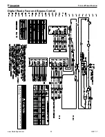
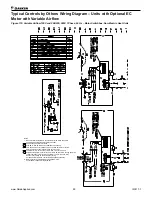
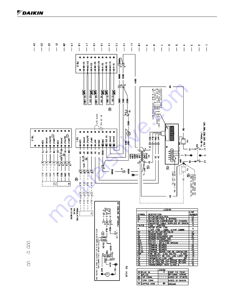
Typical Controls by Others Wiring Diagram – Units with Optional EC
Motor with Variable Airflow, Valve Control
Figure 120:
Variable Airflow 120V, 208/230, 265V 1 Phase, 60 Hz – Terminal Board for Field Controller, Valve Control
Notes:
1. Make electrical installation in accordance with job wiring
schematic complying with national and local electric codes.
2. Automatic temperature control supplier is responsible to
ensure controls operate correctly and protect the unit.
3. Cap all unused transformer leads.
4. X3 unused terminal (2) or (3) must be insulated.
5. Fuse FB, wire 56 & 57 furnished on 208/230 volt units only.
6. 1K thermistor is positive temperature coefficient, 10K thermistor
is negative temperature coefficient.
7. Actuators, 24VAC for 2 to 10 VDC control input.
For a 4 to 20 mA input control signal, add a 500 Ohm resistor
across WHT and BLK.
Output signal of 2 to 10 VDC for position feedback.
8. Cord furnished on right hand connections.
9. Motors are factory programmed for 0-2 VDC OFF, with 2 volts
at 50% nominal and 10 volts at 100% PWM.

